Page: 4-54
WALKER MANUFACTURING COMPANY
July 2006
SERVICE INSTRUCTIONS
Blade Clutch (PTO) - Model MW
Clutch Disengagement/Brake Action
The blade brake is activated by linkage to the clutch
pulley mechanism. The brake is designed to stop the
blades within five (5) seconds after disengaging the
clutch.
Use the following procedure to check and adjust clutch
disengagement and brake action:
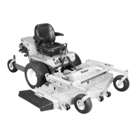
1. Evenly adjust the nuts on the end of the brake band
to achieve 1/4" of travel of the PTO gearbox as-
sembly between the engaged and the disengaged
position (refer to PTO Gearbox Engagement
Photo).
PTO Gearbox Engagement
(view from underside of tractor)
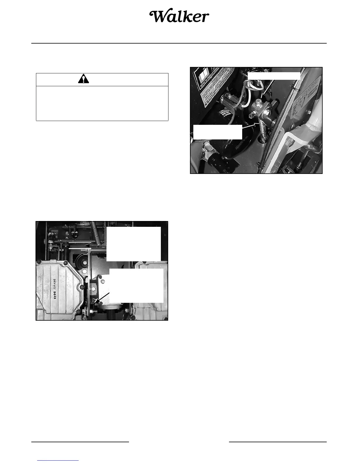
2. Use the adjustment nut on the PTO clutch actuator
assembly (refer to PTO Clutch Linkage Adjust-
ment photo) to set the tension applied by the PTO
clutch lever. The adjustment nut is initially set to
achieve an approximate measurement of 2-3/4"
between the jam nut and the knuckle joint. As the
belt and pulleys wear, it will be necessary to tighten
the adjustment nut in order to prevent belt slip-
page--this adjustment is the same in the Engaged
and Disengaged positions.
Do not overtighten the adjustment nut. This may cause
damage to the clutch linkage and the PTO belt.
PTO Clutch Linkage Adjustment
Transmission Control - Model MS, MC, MD, MT,
MTL
IMPORTANT: The proper adjustment of the transmis-
sion control stops is essential for efficient operation
and life of the transmission. These stops are properly
adjusted at the factory and should only require readjust-
ment if the transmission or related control linkage is re-
moved or changed.
NOTE: It would not be unusual for a new machine, af-
ter initial 5 or 10 hours of operation, to begin to not trav-
el straight (this is due to the break-in of the
transmissions). In this case, proceed to Straight
Ground Travel Adjustment - Step 4.
IMPORTANT: The following adjustment procedures
are sequential. Check and adjust each function in the
order given.
Set Forward Travel Limit (Stop) - Step 1
1. Move the Forward Speed Control (FSC) lever to
the most FORWARD position.
2. Check clearance of the RH and LH steering lever
actuator arms with the frame and adjust forward
stop bolt so each lever clears the frame by at least
1/16 in. (1.6 mm). Clearance of the arm to the
frame should be checked while applying pres-
sure back on the arm to remove any slack in the
linkage.
3. Tighten the jam nut on the forward travel stop ad-
justing bolt.
WARNING
It is important to check and maintain
blade brake action for safe operation of
the machine.
Brake Band
Adjustment Nuts
Located at Front
of Assembly
(Not Visible)
Assembly Should
Move 1/4" Between
Engaged and
Disengaged
Position
Spring Length
Should be 2-3/4"
Adjustment Nut