11
OPTIONAL ACCESSORIES AND BOARDS
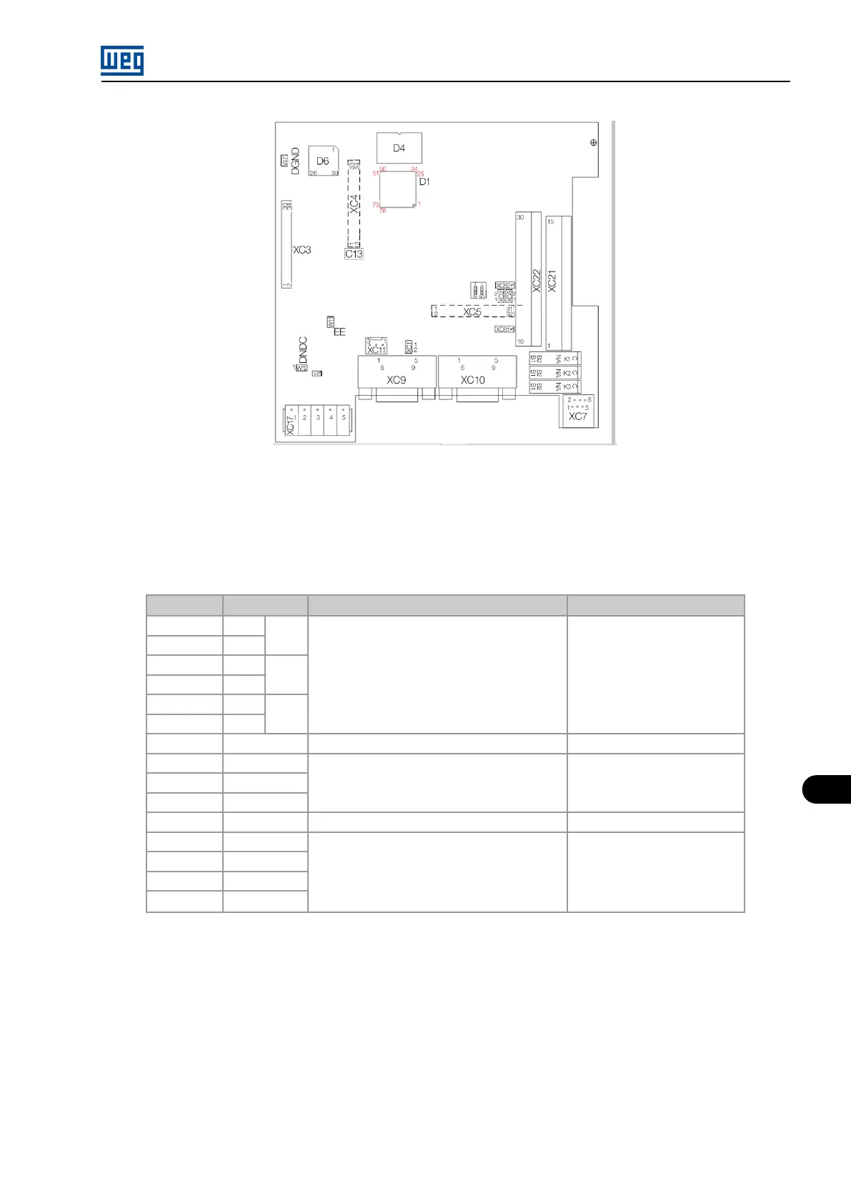
Figure 11.12: PLC2 board connectors
The connectors on the board and the function of their terminals are described below.
XC21 connector: Relay Outputs and Digital Inputs
Table 11.13: Description of the XC2 connector
Connector Function
Description
Specification
1
C
DO1
Digital relay outputs
250 Vac, 3 A
2
NA
3
C
DO2
4
NA
5
C
DO3
6
NA
7 COM DO
Common of the DO4...DO6 digital outputs
-
8 DO4
Bidirectional opto-isolated digital outputs
48 Vdc, 500 mA
9 DO5
10 DO6
11 COM DI
Common of the DI1...DI9 inputs
-
12 DI9
Bidirectional isolated digital inputs
15-30 Vdc, 11 mA @ 24 Vdc
13 DI8
14 DI7
15 DI6
MVW01 | 11-13