10
INSTALLATION, CONNECTION AND ENERGIZATION
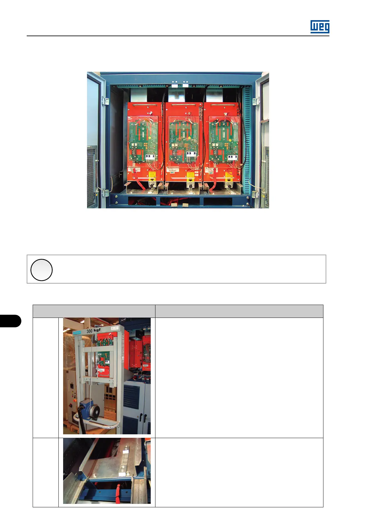
10.1.9 Insertion of the MVW01C Power Arms
Figure 10.9: Power arms inserted in the MVW01C
The power arm insertion must be performed with the help of the transport trolley (WEG part number 11136572), and according to the following
procedure.
✓
NOTE!
During the power arm transport, they must have the locking mechanism engaged.
Table 10.4: Description of the power arm insertion procedure
Picture
Insertion Procedure
1
1. Place the power arm on the transport trolley observing the proper locking
with the locking pin.
2. Lift the arm to the necessary height and bring the trolley close to the
panel.
2
3. Align the trolley guides with the inverter base according to the picture 2.
4. Pay attention to the ISOX board supply cable, which cannot be on the
insertion base in the panel at the moment of the arm insertion.
5. Lock the trolley wheels.
MVW01 | 10-10