11
OPTIONAL ACCESSORIES AND BOARDS
11.1.2 Analog inputs and outputs
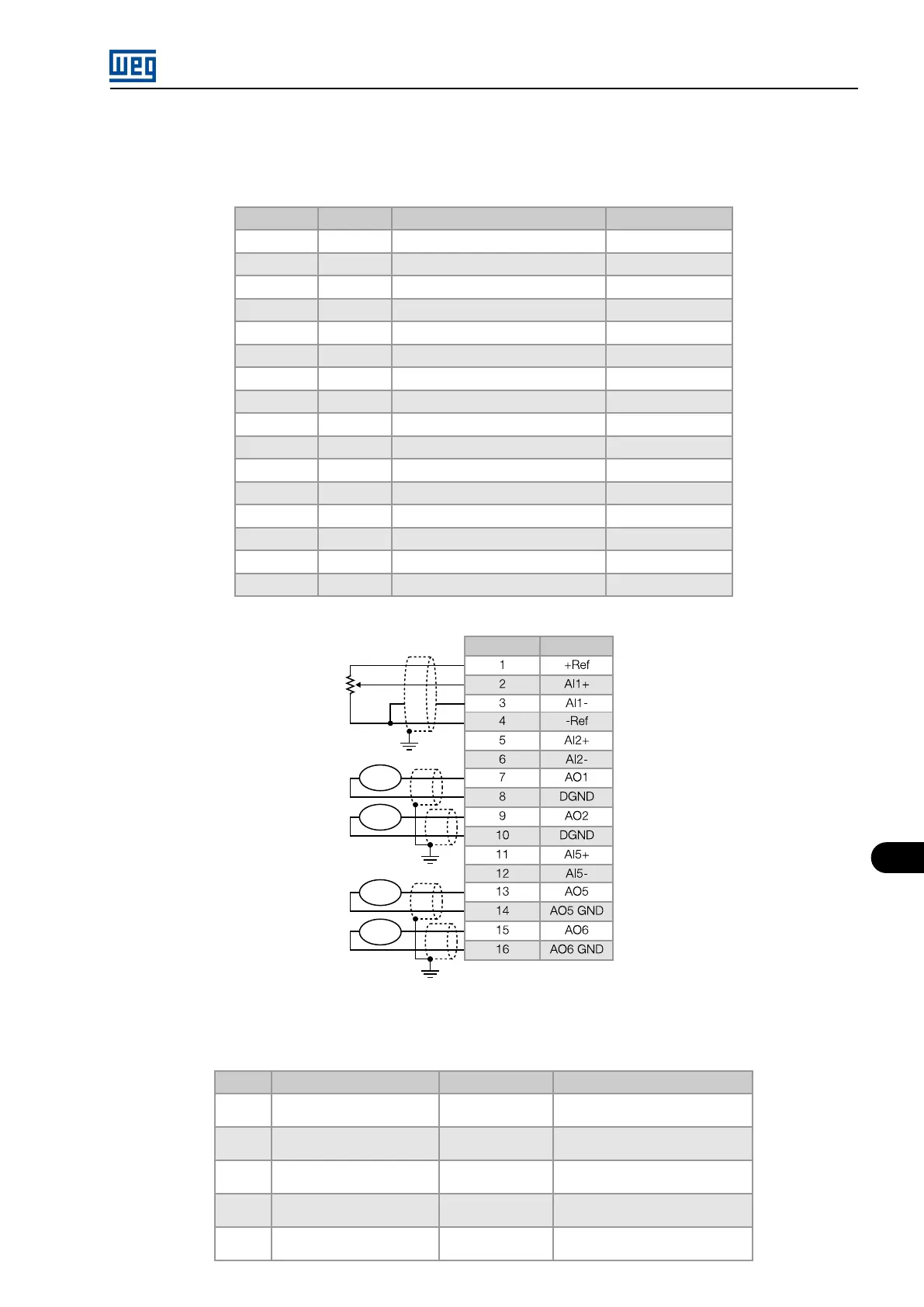
Table 11.2: Description of connector XC1B: analog inputs and outputs
Connector Signal Function (factory default) Specification
1 +Ref Positive reference for potentiometer + 5.4 V ± 5%, 2 mA
2 AI1+ Speed reference (remote) Resolution: 10 bits
3 AI1-
4 -Ref Negative reference for potentiometer - 4.7 V ± 5%, 2 mA
5 AI2+ P0237 = P221/P222 Resolution: 9 bits
6 AI2-
7 AO1 P0251 = Real Speed Resolution: 11 bits
8 DGND 0 V reference for analog output Grounded
9 AO2 P0253 = Output Cur Resolution: 11 bits
10 DGND 0 V reference for analog output Grounded
11 AI5+ P0721 = P221/P222 Resolution: 10 bits
12 AI5-
13 AO5 P0259 = Real Speed Resolution: 11 bits
14 AO5 GND 0 V reference for analog output 5 Grounded
15 AO6 P0261 = Output Cur Resolution: 11 bits
16 AO6 GND 0 V reference for analog output 6 Grounded
Figure 11.3: Description of connector XC1B: analog inputs and outputs
Table 11.3: Switch settings
Signal Function (factory default) Setting Element Selection
AI1 Speed reference S2.A
OFF - (0 to 10) V
ON - (0 to 20) mA / (4 to 20) mA
AI2 P0237 = P221/P222 S2.B
OFF - (0 to 10) V
ON - (0 to 20) mA / (4 to 20) mA
AI5 P0721 = P221/P222 S3.A
OFF - (0 to 10) V
ON - (0 to 20) mA / (4 to 20) mA
AO5 P0259 = Real Speed S4.A
OFF - (0 to 20) mA
ON (4 to 20) mA
AO6 P0261 = Output Cur S5.A
OFF - (0 to 20) mA
ON (4 to 20) mA
MVW01 | 11-3