11
OPTIONAL ACCESSORIES AND BOARDS
11.3.1 EBA/EBB Boards
When the EBA or EBB board is used, the selected encoder should have the following characteristics:
Power supply voltage: 12 Vdc, less than 200 mA current consumption.
2 quadrature channels (90º) + zero pulse with complementary outputs (differential):
Signals A, /A, B, /B, Z e /Z;
Linedriver or ”Push-Pull” output circuit type (12 V level);
Electronic circuit isolated from the encoder frame;
Recommended number of pulses per revolution: 1024 ppr.
Follow the recommendations bellow when mounting the encoder on the motor:
Coupling the encoder directly to the motor shaft (using a flexible coupling, however without torsional flexibility);
Both the encoder metallic housing and the shaft must be electrically isolated from the motor (minimum spacing: 3 mm);
Use good quality flexible couplings that prevent mechanical oscillations or “backlash”.
For electrical connection, use a shielded cable, keeping it as far as possible (> 25 cm) from other wiring (power, control etc.). Preferably, inside
a metallic conduit.
During start-up, it is necessary to program parameter P0202 (Control Type) = 4 (Encoder) to operate with speed feedback by incremental
encoder.
For further details on vector control, see the programming manual available for download on
www.weg.net
.
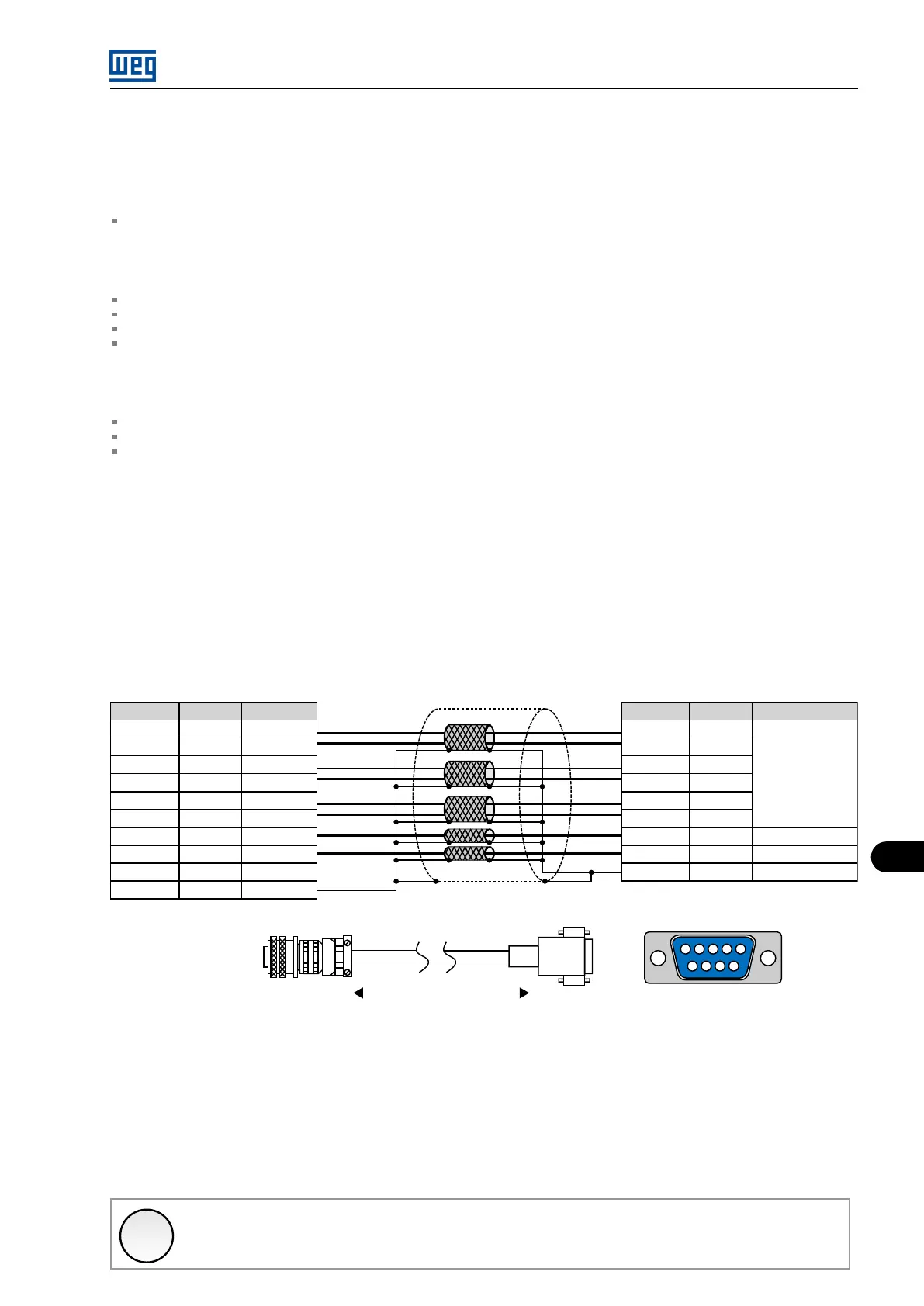
The function expansion boards EBA and EBB have an encoder signal repeater, isolated and externally powered.
Encoder
(3)
A
H
B
I
C
J
D
F
E
G
Signal
A
/A
B
/B
Z
/Z
+VE
COM
NC
Ground
Colour
Red
Blue
Yellow
Green
Gray
Pink
White
Brown
XC9
3
2
1
9
8
7
4
6
5
Signal
A
/A
B
/B
Z
/Z
+VE
COM
Ground
Description
Signal
encoder
Source
(1)
Reference 0 V
(2)
Ground
Maximum recommended length: 100 m (300 ft)
Encoder
1 2 3 4 5
6 7 8 9
EBA or EBB board
XC9 connector (DB9 male)
(1) Encoder power supply 12 Vdc 200 mA;
(2) Referenced to ground with 1 uF parallel to 1 kOhm;
(3) Valid pinout for encoder HS35B Dynapar;
For other models of the encoder verify the correct connection to comply with the necessary sequence.
Figure 11.14: EBA and EBB encoder input.
✓
NOTE!
The maximum allowed encoder signal frequency is 100 kHz.
MVW01 | 11-15