8
INVERTER PARALLELISM
8.3 PARALLELISM OF 2 FRAME D OR 2 FRAME E
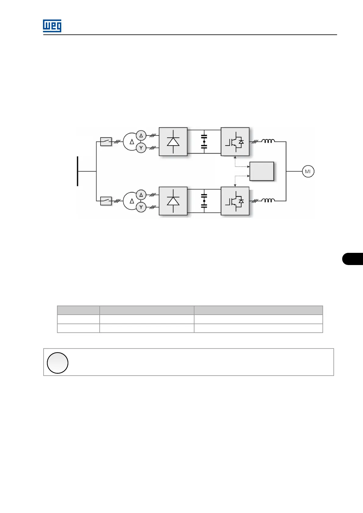
The MVW-01 up to 30690 HP consists in the parallel association of two MVW-01 inverter sets of frame size D or E. The power structures are
associated normally through the use of reactors and differ basically because of the use of two separated DC links fed by distinct secondary
windings (or by using two completely independent transformers).
The main difference of this line compared to the other frame sizes that use parallelism is due to the use of two control sets of the size D or E,
operating in parallel mode and a central control rack managing the combined and synchronized operation of the parallel inverters.
Power
supply
Input
transformer
Multipulse
rectifier
DC
link
Inverter
Parallel 1
Parallel 2
Control
Central
Figure 8.3: General diagram for the 2 x D and 2 x E models
This structure is necessary to increase the total number of inverter power arms, and in this system two inverters in parallel can be used,
which, with the command of an auxiliary control rack equipped with specific software enables the operation of the system as a whole. The
nomenclature regarding the power cell groups was maintained for parallel inverter, just like the parameters and the faults.
The control for the line up to 2 x E presents the need to use 3 HMIs, being one of them for the central rack whereas the two other present
information regarding individual readings and faults of the parallel racks. Table 8.3 on page 8-3 lists the readings that are exhibited differently
in the HMI of the control central.
Table 8.3: Admissible power according to the number of groups used in parallel inverter in the 3300 V and 4160 V line
Parameter
Parallel HMI (standard)
Central Control Rack HM
P0003
Motor Current
Addition of the parallel inverter currents
P0004
DC Link Voltage Highest voltage among the parallel DC links
✓
NOTE!
The faults and alarms are entirely described in the programming manual available for download on www.weg.net.
The connection between the Control Central/Parallels commands can be performed according to the diagrams of Figure 8.4 on page 8-4 or
Figure 8.5 on page 8-4 .
MVW01 | 8-3