12
SPECIAL FUNCTIONS
✓
NOTE!
Observe the polarity of the analog ones at the moment of the connection between the inverters.
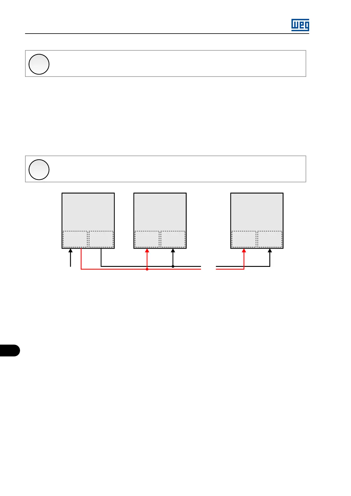
12.1.3 Limitation of the Torque Current - Operation in Vector Mode
As in the previous mode, the main inverter operates in speed control mode, while the auxiliary inverter operates in torque current regulation
mode. Besides the limit value of the torque current, the auxiliary inverter(s) receives the speed reference signal; therefore, in a potential situation
of sudden load reduction, the speed reference is saturated, thereby avoiding a possible sudden acceleration of the motor.
The speed reference signal sent to the auxiliary inverter(s) must be set to a value slightly above the main inverter reference. It is recommended
to apply an offset to the analog inputs of the auxiliary (s) greater than 5 % added to the reference sent by the main inverter; the ideal value may
vary according to the application.
✓
NOTE!
As the operation with negative torque reference is impossible, this method cannot be used for regenerative inverters or with
dynamic braking.
...
...
...
MVW01 MVW01
Auxiliary 1
MVC3
AOX
Torque ref.
Speed ref.
MVW01
Auxiliary n
MVC3
AIX
MVC3
AIX
Speed ref.
Main
AOX
MVC4
AIX
MVC4
AIX
MVC4
Figure 12.2: General operation scheme of the function
Therefore, the inverters must be parameterized as follows:
Main inverter:
Parameterize one of the analog outputs of the MVC3 board to send the torque current limit to the auxiliary inverter(s). The example below
shows the parameterization of analog output AO1 of the MVC4 board to send the speed reference.
P0652 (Analog Output 1 Function – MVC3) = 188 (Inverter torque reference).
P0251 (Analog Output Function 1 – MVC4) = 0 (Speed reference).
Auxiliary inverter:
The auxiliary inverter(s) requires the parameterization of an analog input of the MVC3 board to receive the torque current limit sent by the main
inverter. For the speed reference, use the analog input AI1 of the MVC4 board, whose standard function is the speed reference signal.
P0740 (Analog Input 1 Function - MVC3) = 2 (ICur. Lim.).
P0221 ou P0222 (Speed Reference Selection Local/Remote Situation) = 1 (AI1 - MVC4).
P0236 (Input AI1 Offset) = 5.0 %.
P0133 (Minimum Speed Reference) = set according to the application.
P0134 (Maximum Speed Reference) = set according to the application; it must be 5 % above the maximum limit of the main inverter.
MVW01 | 12-2