4
MVW-01 WITH 5 LEVELS (5L)
Table 4.1: Nomenclature regarding the rectifier parameters used for each H bridge
H bridge reference
phase
Nomenclature Parameter
U
TEMP R1
P0059
V TEMP R2
P0088
W
TEMP R3 P0089
Table 4.2: Nomenclature regarding the rectifier and DC bus parameters used for each H bridge
H bridge reference
phase
Nomenclature Parameter
U
Vdc (+) U
P0053
Vdc (-) U
P0052
V
Vdc (+) V
P0093
Vdc (-) V
P0092
W
Vdc (+) W
P0095
Vdc (-) W
P0094
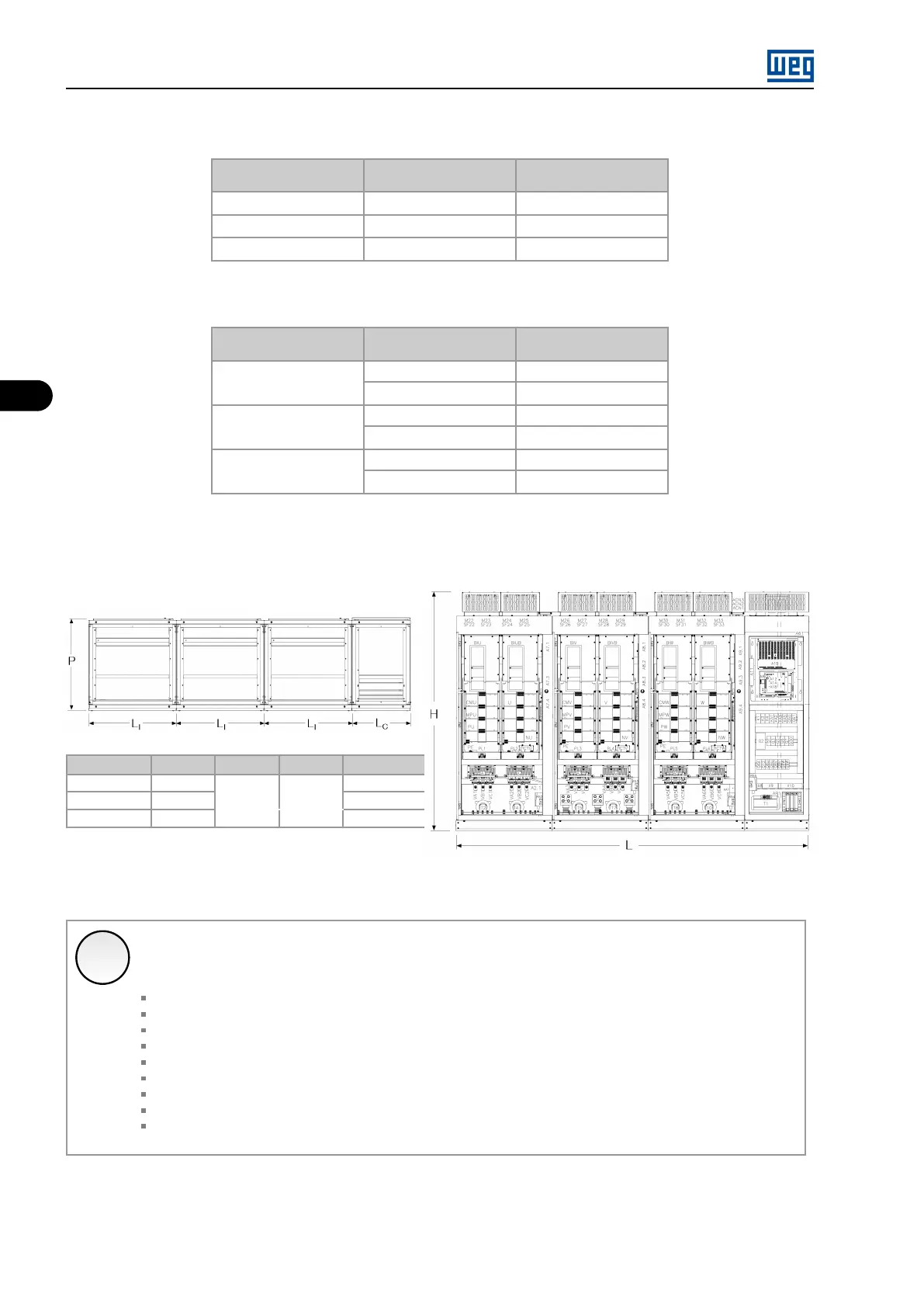
4.1 MECHANICAL DATA
Frame size
L (mm) H (mm) P(mm)
Weight (kg)
C1
3300
2700
C2
8280 2220 1000
4100
C3
10180
5500
Figure 4.2: Dimensions of the complete panel
✓
NOTE!
The values shown in Figure 4.2 on page 4-2 are standard values, however, they may change due to the special characteristics
of the product:
Input Switchgear;
Columns for dynamic braking;
Exciter column (for synchronous machines);
Output filters;
Input filters (AFE);
Additional inverter column (AFE);
Additional column for cables connection (input and output);
Special grounding and safety systems;
Special cooling system (air/water);
4.2 AVAILABLE MODELS
See Item 2.3.1 Available Models on page 2-5 .
MVW01 | 4-2