12
SPECIAL FUNCTIONS
12 SPECIAL FUNCTIONS
12.1 LOAD SHARE FUNCTION “MAIN/AUXILIARY”
Conveyors belts and overhead cranes are classic examples of applications where the torque or position control is used to maintain the conveyor
belt voltage within the limits during the operation, start and stop procedures or even in the transportation of materials in a rising of falling slope.
For motors connected to the same load, it is necessary to ensure a reliable load sharing. Such characteristic is best achieved with the use of
multiple inverters operating in speed reference mode (Main) and torque limitation mode (Auxiliary (s)).
12.1.1 Implementation Modes
Three modes to implement the load sharing function will be presented: Torque Reference, Limitation of the Torque Current and Negative Slip.
Torque reference mode and current limiting mode are for high performance applications, it is mandatory that the inverters involved in the
process be set to vector operating mode. Examples of high performance applications are: conveyor belts, mills (dual pinion, HPGR, SAG,
BALL), overhead crane and lifting. For most applications, vector operating mode with speed or position sensor is recommended.
The negative slip operating mode is for scalar control and is used exceptionally in low dynamics/performance applications. In this operating
mode, all inverters must receive the same speed reference signal, this type of load sharing is called “droop” or negative slip.
In order to implement the load sharing, the inverter assigned as main controls the load speed using all the other inverters of the process as
actuators.
The three implementation methods and the main parameters used in each method are shown below.
12.1.2 Torque Reference - Operation in Vector Mode
One of the possible ways to implement the load sharing function is by parameterizing the salve inverter(s) to follow an external torque reference,
which will be sent by the main inverter.
...
...
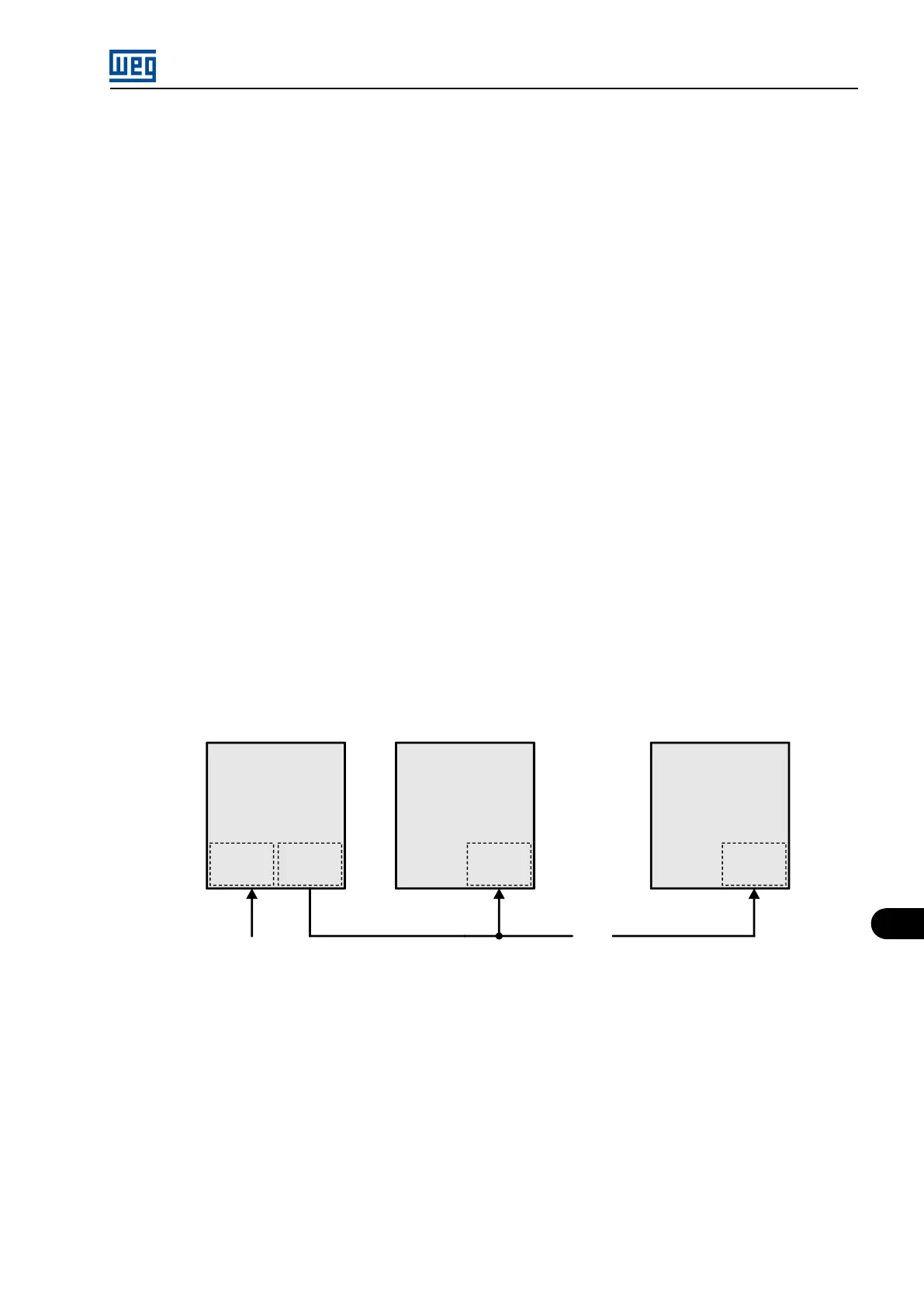
MVC3
AOX
MVW01
MVC3
AIX
MVW01
Auxiliary n
MVC3
AIX
Main
Torque ref.
Speed ref.
MVC4
Auxiliary 01
MVW01
Figure 12.1: General operation scheme of the function
In order to do so, the inverters must be parameterized as follows:
Main inverter:
Parameterize one of the analog outputs of the MVC3 control board to send the torque reference to the auxiliary (s) inverter(s). In the example
below, the analog output AO1 is parameterized.
P0652 (Analog Output 1 Function) = 188 (Inverter torque reference).
Auxiliary (s) inverter (s):
On the auxiliary inverter(s), it is necessary to parameterize an analog input of MVC3 board to receive the torque reference sent by the main
inverter.
P0740 (Analog Input 1 Function) = 1 (Torque reference).
MVW01 | 12-1