10
INSTALLATION, CONNECTION AND ENERGIZATION
Y detail
Sinker 3/8"x3,3/4"
300
140
80
75 75 75
80
450
(3)
75 75
75
L
R
L
i
L
c
20 30
(3)
140
240
(3)
450
80
410
140
300
(3)
30
20
Dash
Dash
80
80
Dash
Dash
Dash
Base = 900
Panel = 900
{Corte AB
20
3/8
80
30
A B
13
L
Notes: (1)
(2)
(3)
Standard TBG-269
Guiding instructions, consult specific project
Panel base ground fixation points
Designer's
criteria
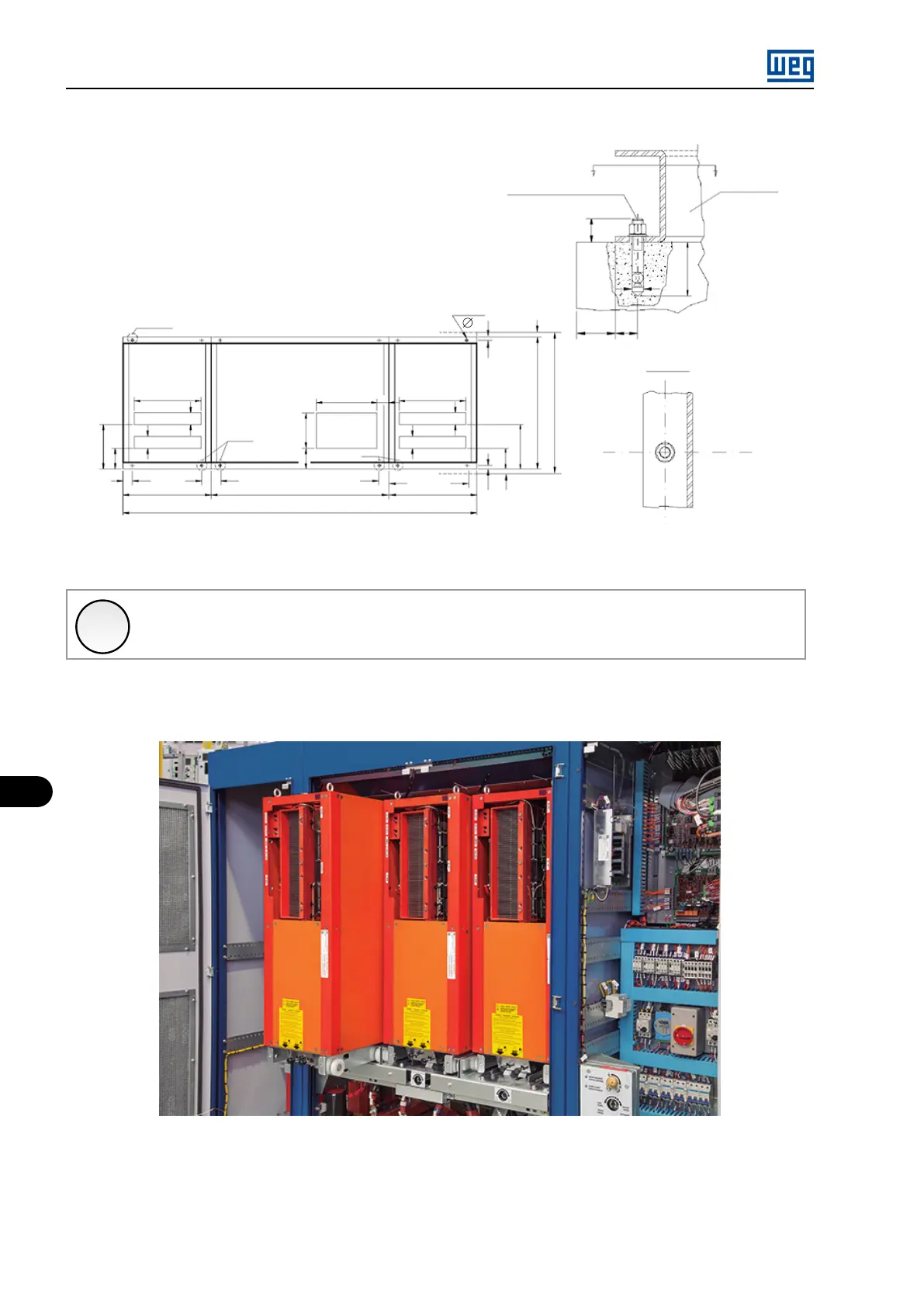
Figure 10.4: Anchoring the MVW01 panel to the floor
✓
NOTE!
Recommendations for anchoring the panel may vary for the several MVW01 models.
For more information refer to the specific project documentation.
10.1.7 Power Arm Insertion
Figure 10.5: Power Arm
MVW01 | 10-6