10
INSTALLATION, CONNECTION AND ENERGIZATION
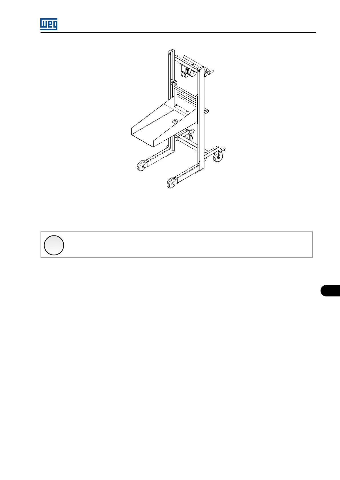
Figure 10.6: Power arm insertion/extraction/movement trolley
The power arm insertion must be performed with the help of the transport trolley (WEG part number 11136572), as shown in Figure 10.6 on
page 10-7 and according to the following procedure.
✓
NOTE!
During the power arm transport, they must have the locking mechanism active and be transported close to the floor (Fig-
ure 10.7 on page 10-8 - foto 1).
1. Rotate the crank handle until the trolley reaches the floor level.
2. Push the arm onto the trolley rails and activate the locking mechanism.
3. Move the transport trolley close to the panel, lifting the power arm to the required height and insert the trolley tabs at the position shown
in (Figure 10.7 on page 10-8 - pictures 1, 2 and 3.
4. Lock the trolley wheels.
5. Release the lock that secures the arm to the trolley (Figure 10.7 on page 10-8 - picture 4) and push it observing the alignment of the
wheels with the base in the panel.
6. The arm must be manually inserted until the locking system (locking pin) is activated (Figure 10.7 on page 10-8 - picture 5).
7. The final insertion stage is done using a crank handle, continuing the insertion to the point the second locking pin engages (Figure 10.7
on page 10-8 - pictures 5 and 6).
MVW01 | 10-7