11
OPTIONAL ACCESSORIES AND BOARDS
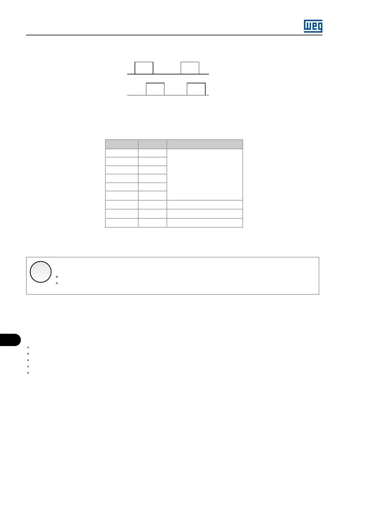
Encoder signal sequence
Time
Time
B
A
Clockwise rotating motor
Figure 11.15: Encoder Signals
Table 11.15: Encoder signal repeater output
Connector Signal Description
3 A
Encoder Signals
2 /A
1 B
9 /B
8 Z
7 /Z
4 +V (*)
Power Supply
6 COM 1 (*)
Reference 0 V
5 Ground
Grounding
(*) For 5 V to 15 V external power supply, consumption 100 mA @ 5 V, excluding the outputs.
✓
NOTE!
Optionally, the external power supply may be connected via XC4:19 and XC4:20 (EBA) or XC5:19 and XC5:20 (EBB);
Encoder Signals Line Driver differential (88C30). Average current value: 50 mA High level.
11.3.2 EBC1 Board
When the board EBC1 is used, the selected encoder should have the following characteristics:
Power supply voltage: 5 V to 15 V;
2 quadrature channels (90 º) with complementary outputs (differential): Signals A, A, B and B;
”Linedriver” ou ”Push-Pull” output circuit type (with identical level as the power supply voltage);
Electronic circuit isolated from the encoder frame;
Recommended number of pulses per revolution: 1024 ppr.
INSTALLATION OF THE EBC1 BOARD
The EBC board is installed directly on the MVC4 control board, secured by means of spacers and connected through the XC3 connector.
Mounting instructions:
1. De-energize the control rack;
2. Carefully insert the XC3 pin bar connector (EBC1) into the XC3 female connector on the MVC4 control board; Check the exact match
of all the pins of the XC3 connector;
3. Press the center of the board (near XC3) until the connector is completely inserted;
4. Secure the board to the 2 metallic spacers with the 2 provided bolts.
MVW01 | 11-16