12
SPECIAL FUNCTIONS
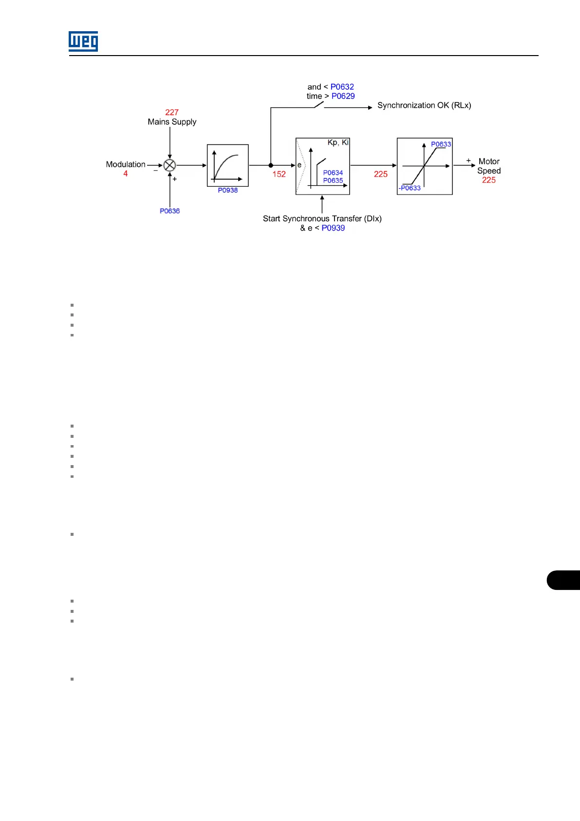
Figure 12.5: Operation diagram of the synchronous bypass function
12.2.2 Important Signals for Analog Outputs
P0652, P0654, P0656, P0658 = 4 ( modulation angle ).
P0652, P0654, P0656, P0658 = 152 ( angular error filtered by P0938 ).
P0652, P0654, P0656, P0658 = 225 ( diagram frequency output ).
P0652, P0654, P0656, P0658 = 227 ( power grid angle ).
12.2.3 Possible Failures
A0008 – Timeout of synchronous transfer
Rectifier phases at measuring point out of correct sequence (UWV).
Wrong direction of rotation of the motor.
P0630 – Time for synchronous transfer too short.
P0633 – Search limit for synchronous transfer too low, causing small range of action in search of synchronism.
P0634 and P0635 – Synchronous transfer searcher regulator causing oscillation in synchronism seek.
P0101 and P0103 – Acceleration time too long, causing search delays.
Improper Indication for Synchronism Ok
P0629 – Time for synchronization programmed to a minimum. In this case, the inverter will immediately signal synchronism OK when the
angle error is within the value programmed in P0632.
F0070 - Overcurrent (During Transfer)
P0400 – Incorrect motor rated voltage, performing the bypass with wrong RMS voltage.
P0636 – Incorrect output phase adjustment, causing the bypass to be out of phase.
P0631 – Very long delay in the ”Fast Disable” actuation, causing the inverter to remain in parallel with the grid for a very long period.
No Voltage on the Motor (During Transfer)
P0631 – A very short delay in the ”Fast Disable” actuation, causes the inverter to be disabled before the bypass circuit breaker has
completed closing its contacts.
MVW01 | 12-5