13
DIAGNOSTICS AND TROUBLESHOOTING
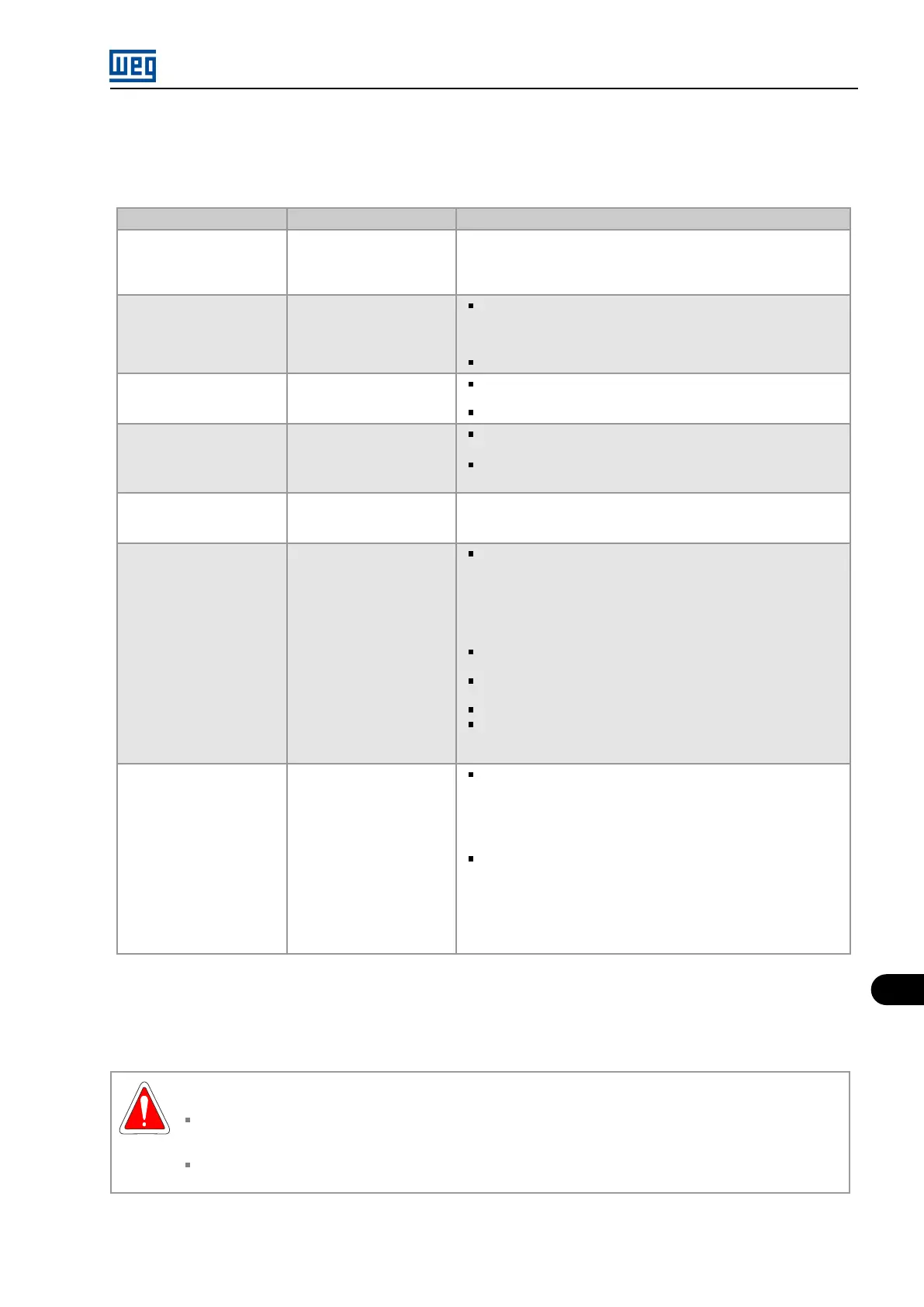
Table 13.1 on page 13-3 shows the periodic preventive maintenance procedures under operation condition.
Table 13.1: Intervals and procedure of the preventive maintenance in operation
Interval Items Procedure
1 month after start-up Monitoring parameters
Check if the inverter is operating within the project specifica-
tions: input transformer secondaries voltage (VSEC = VLINK /
1.35 in each power cell) and output current (P0003). Change
the position of the main transformer taps if necessary.
Every 3 months
Cleaning (or
replacement) of the air
filters
(1)
Remove all filters from the panel and clean them with an air
blower or with compressed air, or wash them with neutral de-
tergent and dry them well, before installing them back into the
panel;
Replace all filters if cleaning is not efficient.
Every 3 months
Visual inspection of the
ventilation
Check if the flaps of the exhausters are open. Check the
rotation direction of the exhausters in panels without flaps;
Check the rotation direction of the control panel fan.
Every 3 months
Upload of the Log of
Faults and Alarms
Make a backup of the inverter complete programming. Follow
the WPS
©
software instructions;
Upload the Log of Faults and Alarms (P0067). Follow the
WPS
©
software instructions.
Every 3 months Date and time setting
Adjust the current date and time, if necessary. Use the param-
eters P0080 (Date) and P0081 (Hour) by the Graph HMI V2 or
the menu Settings by the Graph HMI V3 (touchscreen).
Every 3 months
Visual inspection of the
control panel
Electronic boards:
– Check for excessive dust accumulation or any accumulation
of conductive particles or humidity;
– Check for heating spots (discolouration or blackening of com-
ponents);
– Check for leakage or deformation (expansion) of the body of
electrolytic capacitors.
Pre-charge resistors: check for heating spots (discoloura-
tion or blackening);
Flat cables and internal wiring: check for heating spots (de-
formation, discolouration or blackening);
Internal and signal lights: check the operation;
Space heater cord: check the operation. If there is a thermo-
stat, adjust the temperature to turn it off between 5 and 10 °C
above the medium temperature of the electrical room.
Every 3 months
Basic measurements on
the control panel
Auxiliary power supplies:
– Measure the voltages L1, L2 and L3 of the auxiliary power
supply and check if it is within the +10/-15% tolerance;
– Measure the auxiliary single phase supply for space heaters,
sockets and lamps (if separate) and check if it is within the +10/-
15% tolerance.
PSS24 power supply:
– Measure the 220 VAC input voltages and check if they are
within the +10/-15% tolerance;
– Measure the 24 VDC output voltage and check if it is within
the ±0.2 V tolerance;
– Measure the temperature on the aluminium base and check if
it is below Tamb + 20 °C (36 °F).
(1) The interval may be extended, according to the electrical room cleanliness, from 3 to 6 or 12 months.
13.2.2 Preventive Maintenance with Complete Stop/De-energization
DANGER!
This equipment has high voltages that may cause electric shocks. Only people with properly qualified and familiar with
the MVW01 Inverter and associated equipment must plan or service this equipment. In order to avoid the risk of shock,
follow all the safety procedures required for servicing energized equipment.
Do not touch any electrical circuit before ensuring it is de-energized.
MVW01 | 13-3