11
OPTIONAL ACCESSORIES AND BOARDS
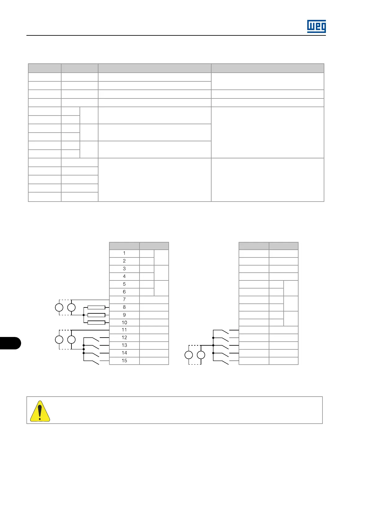
Table 11.14: Description of the XC22 connector
Connector Function
Description
Specification
16 PTC1
Motor thermistor input
Actuation: 3900 Ω, Release: 1600 K
17 PTC2
PTC
Minimum Resistance: 100 Ω
18 GND ENC
Power supply reference for the encoder inputs
-
19 +ENC
Power supply for the encoder inputs 5 Vdc regulator or (8 to 24) Vdc, 50 mA (**)
20
-
AO2
Analog output 2, 12 bits
(-10 to +10) Vcc or (0 to 20) mA
21
+
22
-
AO1
Analog output 1, 12 bits
23
+
24
-
AI1
Differential analog input 1, 12 bits
25
+
26 DI1
Bidirectional isolated digital inputs
15-30 Vdc, 11 mA @ 24 Vdc
27 DI2
28 DI3
29 DI4
30 DI5
NOTES:
NA = normally open contact.
C = common.
Connector Signal
+ENC
DI1
DI2
DI3
DI4
DI5
AO2
PTC1
PTC2
GND ENC
-
+
-
+
-
+
+
-
+
-
(*)
16
17
18
19
20
21
22
23
24
25
26
27
28
29
30
AO1
AI1
COM DI
Connector Signal
NA
COM DO
DO4
DO5
DO6
COM DI
DI9
DI8
DI7
DI6
DO3
C
N
C
C
NA
DO1
DO2
+
-
+
-
+
-
+
-
(*)
(*)
Figure 11.13: Description of the XC21 and XC22 connectors
WARNING!
(*) External power supply.
(**) For current, S1 switch must be ON.
11.3 INCREMENTAL ENCODER
Applications that require more speed or positioning accuracy, a speed feedback of the motor shaft by means of incremental encoder is required.
The connection to the inverter is made through the XC9 connector (DB9) on the EBA function expansion board, or XC9 on EBB, or XC10 on
EBC.
MVW01 | 11-14