3
MVW01 WITH 3 LEVELS (3L)
Considering the standard rectifier version (12 pulses) the secondary winding voltage depends on the motor nominal voltage, being 2.2 kV for
motors with 4160 V rated voltage, and 1.75 kV for motors with 3300 V rated voltage. The 6 cables enter the rectifier cabinet at the top or at
the bottom and are connected directly to terminals mounted on the rectifier module (A1) copper bars.
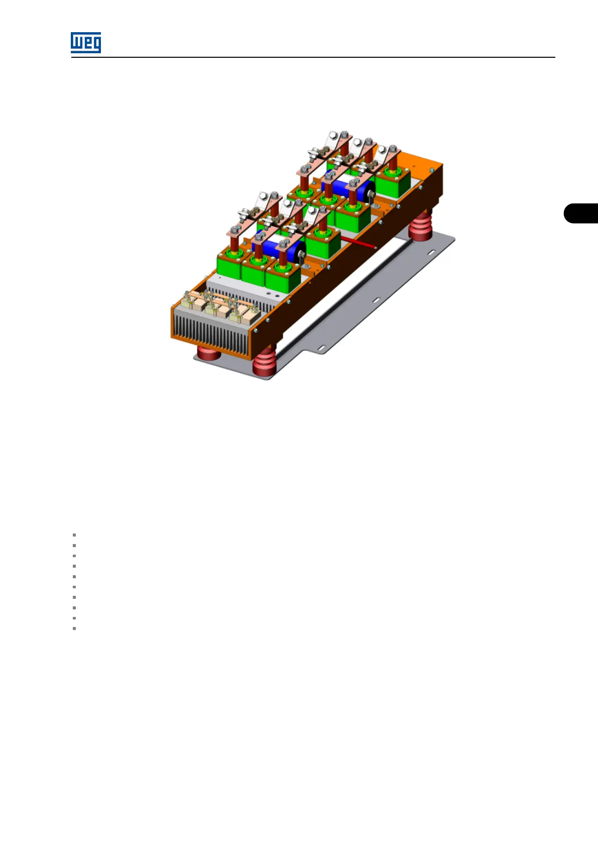
Figure 3.4: MVW01 12-pulse rectifier
The rectifier is connected to the DC link located at the rear part of the MVW01 panel. The DC bus supplies the voltage for the three inverter
power arms.
3.3 INVERTER ARMS
The inverter arms are identical and contain:
4 or 6 filtering capacitors (of dry plastic film).
4 medium voltage IGBT modules.
1 medium voltage diode module.
1 power heatsink.
4 gate driver boards (one for each IGBT).
4 isolated DC/DC converters (gate driver boards power supply).
1 heatsink temperature sensor (NTC resistor).
1 NPC resistor.
1 ISOC.02 Signal feedback board.
2 resistors for balancing the DC Bus.
The arm has a mechanical structure formed by bulk molding compound (BMC) (polyester resin and fiberglass).
The singers/pinchers located at the back of the inverter cabinet make the electrical connection of the arms to the busbars Describes the arm
transportation and installation procedures Chapter 10 INSTALLATION, CONNECTION AND ENERGIZATION on page 10-1 .
MVW01 | 3-5