9
SUPPORTED MOTORS
9.2.2 FIELD SET (DC WITH BRUSHES)
The field excitation of the synchronous motor can be done through an AC-DC converter that presents the possibility of being controlled by a
control loop, and that has an input for current reference and presents an analogue output with the information of its output current (feedback
for the MVW01 ).
Specifications:
Current reference input AC-DC: 0 to 10 V (CA-CC 5 V = 1 PU, observe P0462);
Feedback of the output current for the MVW01 : 0 to 10 V (MVW01 5 V = 1 PU, observe P0462 and P0744).
✓
NOTE!
The MVC3 board has only voltage signals, in order to use current signals an external current transducer must be used.
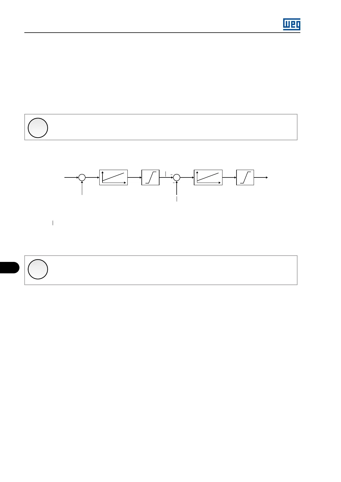
Example of configuration of the field current reference and paremeter setting of the inverter is presented in Figure 9.6 on page 9-4 , the
parameters presented are described in the Programming Manual available at www.weg.net.
= Modulation index
= Stator flux
= Stator flux, module
= Field current reference
P0180
|m|
+
+
P0182 / P0183 P0178 P0175 / P0176 P0449
P0177 P0450
|0|
i
f
|m|
0
|0|
i
f
0
Figure 9.6: Parameters used by the inverter in the calculation of the of the field current reference
✓
NOTE!
Information presented in Chapter 9 SUPPORTED MOTORS on page 9-1 of this manual refers to the operation of synchronous
machines with DC excitation and with brushes.
In order to drive synchronous machines with other types of excitation, consult WEG.
9.3 PERMANENT MAGNET SYNCHRO MOTORS (PMSM)
The MVW01 is a high-performance product designed also for controlling smooth-pole permanent magnet (PMSM) synchronous motors.
Application of smooth pole permanent magnet motors (PMSM) becomes attractive due to performance, high rotation, power density, and
efficiency, is widely used in deep-sea oil extraction applications and motor applications at high speed.
The control method used by the MVW01 is voltage vector control without a position or speed sensor (sensorless). This robust control enables
operation with a unity power factor and maximum utilization of the drive and motor. This control allows operation with maximum torque per
ampere (MTPA) (motors with Ld = Ld).
MVW01 | 9-4