6
MVW01 WC (WATER COOLED)
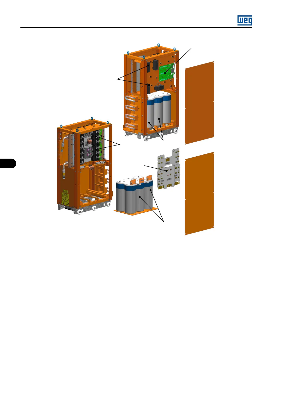
ISOX board
DC/DC converters
Capacitors
Laminated busbar
Capacitors
IGBTs
Figure 6.4: Water cooled power arm MVW01
6.3 CONTROL RACK
The control rack used in the MVW01 WC inverter line has the same functions and uses the same boards of the rack used in the MVW-01 3L
and 5L lines. Consult Section 3.4 CONTROL RACK on page 3-7 .
6.4 WEG COOLING SYSTEM RSW
The operation of the RSW is based on the heat exchange principles among liquids, formed by primary and secondary circuits.
Primary circuit: It is a closed circuit composed of two pumps, a heat exchanger, an expansion tank, flow indicators, flow, temperature, and
pressure sensors, besides that, there are valves for diferente purposes. The pumps are installed in a parallel configuration, and they operate
alternatively pumping the coolant fluid through the circuit. The fluid remove the heat from the inverters and components being cooled and
then transports to the heat exchanger where it transfers it to the secondary circuit. The RSW is controlled by the PLC circuit board of the
frequency inverter (PLC300). The system parameters are collected by sensors and send them to the PLC for controlling the process. The
inverter controls the three-way valve by monitoring the temperature and humidity in order to avoid a large difference in temperature in the
coolant fluid as compared to the environmental temperature that causes condensation. Alarms are also triggered in cases of abnormalities that
result in temperatures exceeding the specified range in the project. The control system commands the alarm and operation of the equipment
by monitoring the flow. As it is a closed system, it is necessary to use an expansion tank (ET) to keep the pressure constant during operation.
If abnormal pressures are detected by the pressure sensor, the control system commands the alarms and the operation of the equipment. The
presence of the over pressure valve avoids that the pressure exceeds 6 bar. The system is also equipped with a leakage sensor.
Secondary circuit: This circuit is responsible for transferring the heat from the primary circuit to the customer’s system using the heat exchanger.
The RSW does not control the parameters of the secondary circuit, as these are the customer’s and/or end user’s responsibility.
MVW01 | 6-4