12
SPECIAL FUNCTIONS
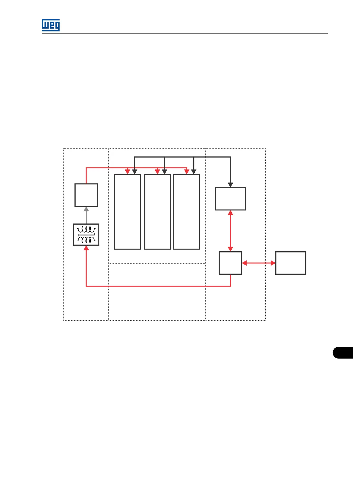
12.3 SAFETY STOP FUNCTION
The Safety Stop function aims at providing the motor with a safe stop mode system through hardware, ensuring that the inverter will not spin
the motor regardless of the software or auxiliary circuit.
12.3.1 Implementation Mode
As the MVW-01 features an auxiliary power supply of the measuring boards and Gate Drivers, it will be necessary to use an exclusive trans-
former/supply set for the Gate Drivers, thus enabling to turn them off independently of the measuring boards.
By turning off this supply we are ensuring that under no circumstances will the system go into operation again. For this purpose, we will use a
safety relay certified for the function, containing inside two independent relays in relation to the drive and contacts.
Auxiliary
supply
PS1S
Phase
arm
U
Phase
arm
V
Phase
arm
W
Control
system of
the inverter
Safety
stop
Safety
Client
control
Figure 12.7: General operation scheme of the function
12.3.2 Hardware
To implement the system, a safety relay certified for this type of function will be used, according to the diagram in Figure 12.8 on page 12-8 .
In order to enable the Safety stop function, it is necessary to command the safety relay directly by commanding any of the emergency buttons
connected in series shown in Figure 12.8 on page 12-8 . The relay, without influence of the inverter, will shut down the power of the Gate
Drivers, inform the control about the change to the safe operating mode and send a feedback to the client.
On the inverter, the digital input DI15 of the MVC3 board (through the PIC board) is configured so that whenever it receives a signal of 24
V (high), the inverter, regardless of the routine it is running, immediately goes into the safe operating mode, inhibits the trigger signals of the
switches and ignores all the IGBT, temperature of the arms and of the PS1 supply faults that may occur at this moment due to the power loss.
From the effective ingress of the inverter into the safe mode, the A165 alarm is signaled on the HMI, informing the inverter is locked for operation
by the Safety Stop function.
On the MVC4 board, the relay outputs (RL1 to RL5) have the option 36 (Safety Stop). Such function provides the indication of the function in
progress. The parameters for configuration of the relay outputs are: P0277, P0279, P0280, P0281 and P0282.
Since this is a safety function, the implementation is performed through a relay that presents actuation redundancy and simultaneity in the
activation mode. Such redundancy is used both in the disconnection of the supply and in the information to the control and feedback to the
client.
MVW01 | 12-7