12
SPECIAL FUNCTIONS
If a fault occurs in one of the internal relays, the system is locked likewise; however, due to its internal self-monitoring, it will not go back into
operation, requiring a check of the cause for the lock. Therefore, the supply of the Gate Drivers is turned off, and the IGBT and/or temperature
of the arms fault and/or PS1 supply fault is indicated, and consequently the entire system is shut down (the main circuit breaker opens) due to
operation fault.
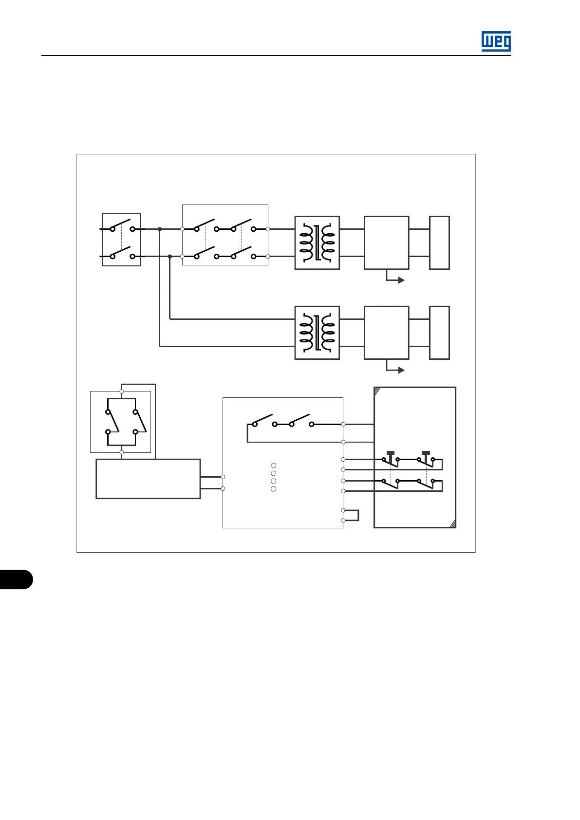
The image below presents the electrical diagram of the Safety Stop function.
TP1
Safety Stop diagram
13
23
14
24
CPA-D
Q3
220/220 V
300 VA / 7,2 kV
PS1S_1
In: 220 Vac
Out: 15 Vdc
FOI N6_BR
Gate drives
PS1S_2
In: 220 Vac
Out: 15 Vdc
220/220 V
300 VA / 7,2 kV
FOI N6_BR_B
Mens. cards
41
CPA-D
42
Xc8:9
11
Di15
24 V
PIC
24 V = safety
0 V = run
Xc8:12
15
A1
+
-
24V
A2
LEDs
PW
S1
S2
Out
Relay instrutech model
CPA-D
CPA-D
Y1
Y2
S11
S12
S21
S22
34
33
Client
Feedback
Open = safety
Close = run
220 Vac
Figure 12.8: Electrical diagram of the Safety Stop function
The system leaves the safety stop function 100 ms after the signal of digital input DI15 is removed, and the inverter begins to monitor all the
faults again, accept commands of enable PWM and reset of alarm A165.
MVW01 | 12-8