13
DIAGNOSTICS AND TROUBLESHOOTING
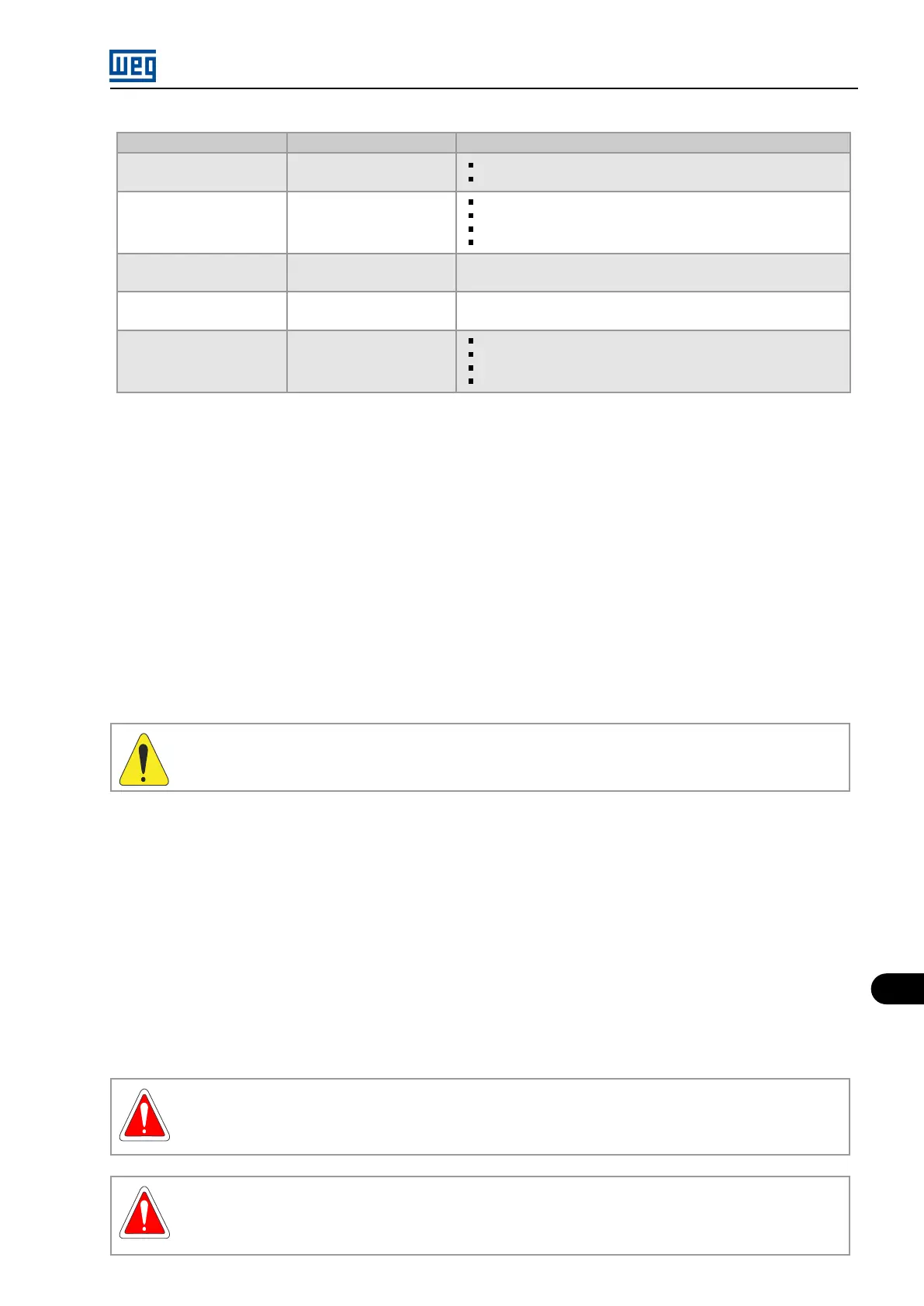
Interval Items Procedure
Every 2 years
Test of the protection
relay
(4)
Test of the selectivity adjustments;
Trip test of the overcurrent output.
Every 3 years
Maintenance of the input
circuit breaker or
contactor
(3)
Insulation resistance;
Lubrication;
Cleanliness;
Heating points etc.
Every 40000 h of
operation
(5)
Replacement of the
exhausters
Replace the exhausters of the power columns and the fan of
the control column.
Every 5 years Power cells clamps
Clean the contacts and clamps with a dry flannel and apply new
conductive grease
(6)
to all clamps.
Every 5000 energizations
Maintenance of the input
circuit breaker or
contactor
(5)
Insulation resistance;
Lubrication;
Cleanliness;
Heating points etc.
(1) The interval may be reduced or extended, according to the electrical room cleanliness, from 6 to 12 or 24 months.
(2) Remove the cells only in case of great dirt accumulation. Use an air blower and antistatic brush. Never use compressed air, as it could
contaminate the cell with oil or humidity.
(3) Recommendation from most medium voltage circuit breakers and contactors manufacturers. Refer to the manufacturer’s documenta-
tion.
(4) Recommendation from most protection relay manufacturers. Refer to the manufacturer’s documentation.
(5) If the inverter is in operation 24/7, 40000 h are approximately 4.5 years.
(6) Conductive grease type PENETROX A, manufacturer BURNDY.
13.3 SAFE DE-ENERGIZATION INSTRUCTIONS
1. Decelerate the motor to a complete stop.
2. Check the DC link voltage values of the installed power cells at parameters P1000 to P1035 da HMI.
3. Press the “POWER OFF” pushbutton. The input transformer switchgear should open at this moment, which is indicated by the “INPUT ON”
pilot light going off.
WARNING!
If the input transformer switchgear does not open with the “POWER OFF” command, then open it manually.
4. Follow the DC link voltage decrease through P004 on the HMI and the HVM neon lamps. When the DC link voltage crosses below 200 V
the neon lamps start flashing with progressively lower frequency until going off completely.
Wait until the DC link voltage displayed at P004 on the HMI gets below 25 V.
5. Press the emergency pushbutton located on the control column door and remove its key.
6. On the circuit breaker cabinet (switchgear) of the input transformer, switch off the switch disconnector and grounding of the inverter circuit. It
is necessary to confirm visually the opening of the switch through the inspection window. Lock the cabinet and/or add warning sign indicating
“System in maintenance”.
7. Switch off the Q2 circuit breaker in the control column and lock it in the open position with a padlock and/or put a warning sign indicating
“System in maintenance”.
8. Switch off the Q1 circuit breaker in the control column. Remove the auxiliary power supply.
It is only after the sequence of procedures described above that high voltage compartment doors can be opened.
DANGER!
If it were not possible to follow the discharge of the DC link capacitors through the parameter P004, as well as through the
HVM board neon lamps, due to a malfunction or a previous, de�energization, follow the instructions 5 through 8 and wait 10
minutes more.
DANGER!
S’il n’était pas possible de suivre la décharge des condensateurs de liaison CC avec le paramètre P004 et les lampes à néon
de la carte HVM en raison d’un dysfonctionnement ou une mise hors tension préalable, suivez les instructions 5 jusqu’à 8 et
attendez 10 minutes supplémentaires.
MVW01 | 13-5