11
OPTIONAL ACCESSORIES AND BOARDS
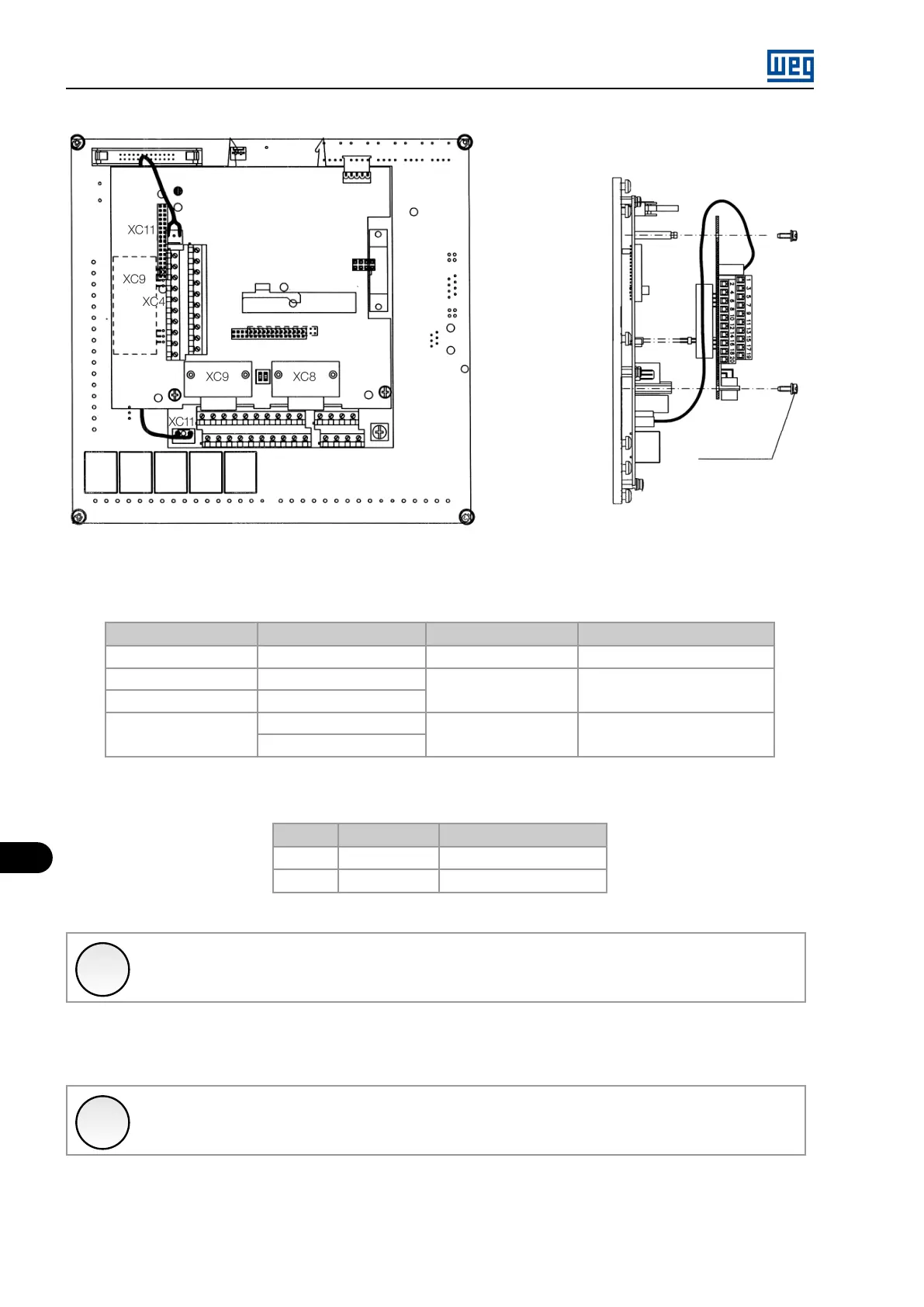
Figure 11.11: Procedure to install the EBB board
Table 11.11: Configurations of the setting elements - EBB board
Setting
Function (factory default)
OFF ON
S4.1
AI3 - P0241 = P221/P222
(0 to 10) V (0 to 20) mA or (4 to 20) mA
S5.1 e S5.2
AO1 - P0251 = Real Speed
(0 to 20) mA (4 to 20) mA
S6.1 e S6.2
AO2 - P0253 = Output Cur
S7.1 e S7.2
RS-485 B - LINE (+)
Without termination
With termination (120 Ω)
RS-485 A - LINE (-)
Table 11.12: Configurations of the setting elements - EBB board
Trimpot Function Function (factory default)
RA5 AO1 - full scale P0251 = Real Speed
RA6 AO2 - full scale P0253 = Output Cur
✓
NOTE!
The external signal and control connection must be fitted to XC5 (EBB) observing the same recommendations as those for
the connection of the MVC4 control board (see Section 11.1 MVC4 SIGNAL AND CONTROL CONNECTIONS on page 11-1 ).
11.2.3 PLC2
✓
NOTE!
For further information, see the specific manual for the PLC2 board.
MVW01 | 11-12