11
OPTIONAL ACCESSORIES AND BOARDS
INSTALLATION
The EBB board is installed directly on the MVC4 control board, secured with spacers and connected via terminal blocks XC11 (24 V) and XC3.
Mounting instructions:
1. De-energize the control rack;
2. Configure the board as desired (switches S4, S5, S6 and S7, referring to Table 11.7 on page 11-8 );
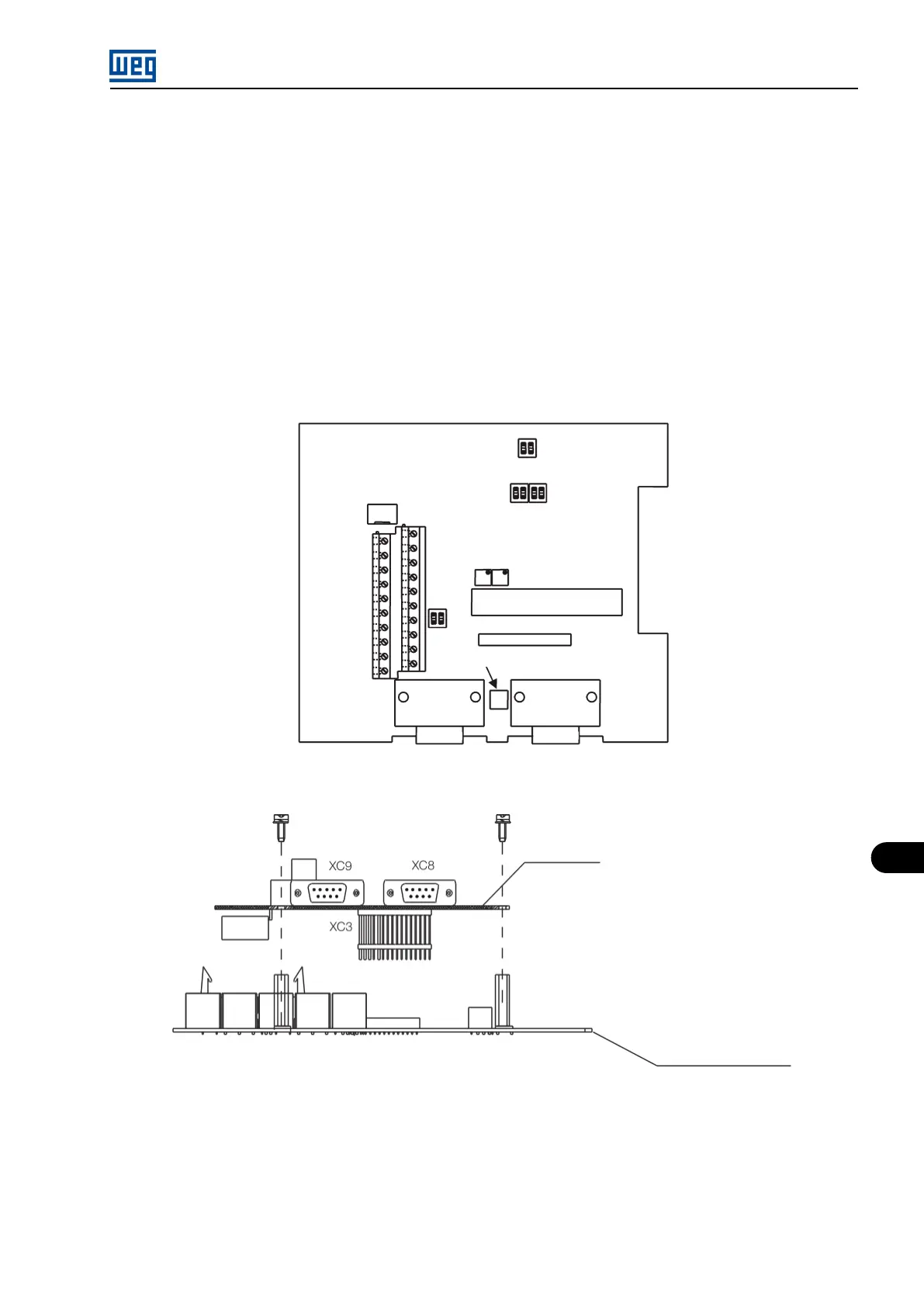
3. Carefully insert the XC3 pin bar connector (EBB) into the XC3 female connector on the MVC4 control board. Check the exact match of
all the pins of the XC3 connector;
4. Press on the EBA board (near to XC3) and on the left top edge until the complete insertion of the connector and the plastic spacer;
5. Secure the board to the 2 metallic spacers with the 2 provided bolts;
6. Fit the XC11 connector on the EBB board to the XC11 connector on the control board (MVC4).
Figure 11.9: Position of the adjustment elements - EBA board
Figure 11.10: Procedure to install the EBB board
MVW01 | 11-11