11
OPTIONAL ACCESSORIES AND BOARDS
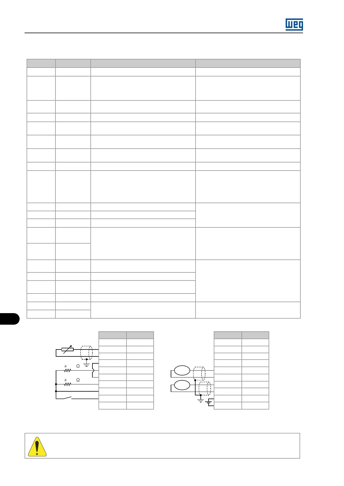
Table 11.10: Description of the XC5 connector (full EBB board)
Connector
Signal
Function (factory default) Specification
1
NC
- -
2
DI8
Input 1 for the motor thermistor - PTC1 (See
P0270)
Actuation: 3.9 kΩ
Release:1.6 kΩ
Minimum resistance: 100 Ω
3
DGND (DI8)
Input 2 for motor thermistor - PTC 2 (See P0270) Referenced to DGND (DI8) through a 249 Ω re-
sistor
4
DGND
0 V reference of the 24 Vdc power supply Grounded via 249 Ω resistor
5
DO1
Transistor output 1: Not used Isolated, open collector, 24 Vdc, max: 50 mA, re-
quired load (Rc) 500 Ω
6
COM
Common point DI7 digital input and DO1 and DO2
digital outputs
-
7
DO2
Transistor output 2: Not used Isolated, open collector, 24 Vdc, max: 50 mA, re-
quired load (Rc) 500 Ω
8
24 Vdc
Power supply for digital inputs/outputs 24 Vdc ± 8% Isolated, Capacity: 90 mA
9
DI7
Isolated digital input: Not used
Minimum high level: 18 Vdc
Maximum low level: 3 Vdc
Maximum voltage: 30 Vdc
Input current: 11 mA @ 24 Vdc
10
SREF
Reference for RS-485
Isolated RS-485 serial
11
A-LINE
RS-485 A-LINE
12
B-LINE
RS-485 B-LINE
13
AI3 +
Analog Input 3: Speed reference
Programmable differential (see P0243)
Resolution: 10 bits (0.1% of full scale)
14
AI3 -
Impedance: 400 kΩ (0 to 10) V
500 Ω [(0 to 20) mA/(4 to 20) mA]
15
AGND
0 V reference for analog output (internally
grounded)
Resolution: 11 bits (0.5% of full scale)
Required load 600 Ω
16
AO1
Analog output 1: Speed
17
AGND
0 V reference for analog output (internally
grounded)
18
AO2
Analog output 2: Motor current
19
+V
External power supply for encoder repeater
output (XC8)
External power supply: 5 to 15 V
Consumption: 100 mA @ 5 V, excluding the
outputs
20
COM 1
Connector
Signal
Rc 500
Rc 500
1
2
3
4
5
6
7
8
9
10
rpm
A
Connector
Signal
11
12
13
14
15
16
17
18
19
20
NC
DI8
DGND (DI8)
DGND
DO1
COM
DO2
24 Vdc
DI7
SREF
A-LINE
B-LINE
AI3+
AI3-
AGND
AO1
AGND
AO2
+V
COM 1
Figure 11.8: Description of the XC5 connector (full EBB board)
WARNING!
The analog input AI3 and the analog outputs AO1’ and AO2’ isolation has the purpose of interrupting ground loops. Do not
connect them to high potentials.
ENCODER CONNECTION: refer to Section 11.3 INCREMENTAL ENCODER on page 11-14
MVW01 | 11-10