11
OPTIONAL ACCESSORIES AND BOARDS
11.1.1 Digital inputs
Table 11.1: Description of the XC1A connector: digital inputs
Connector Signal Function (factory default) Specification
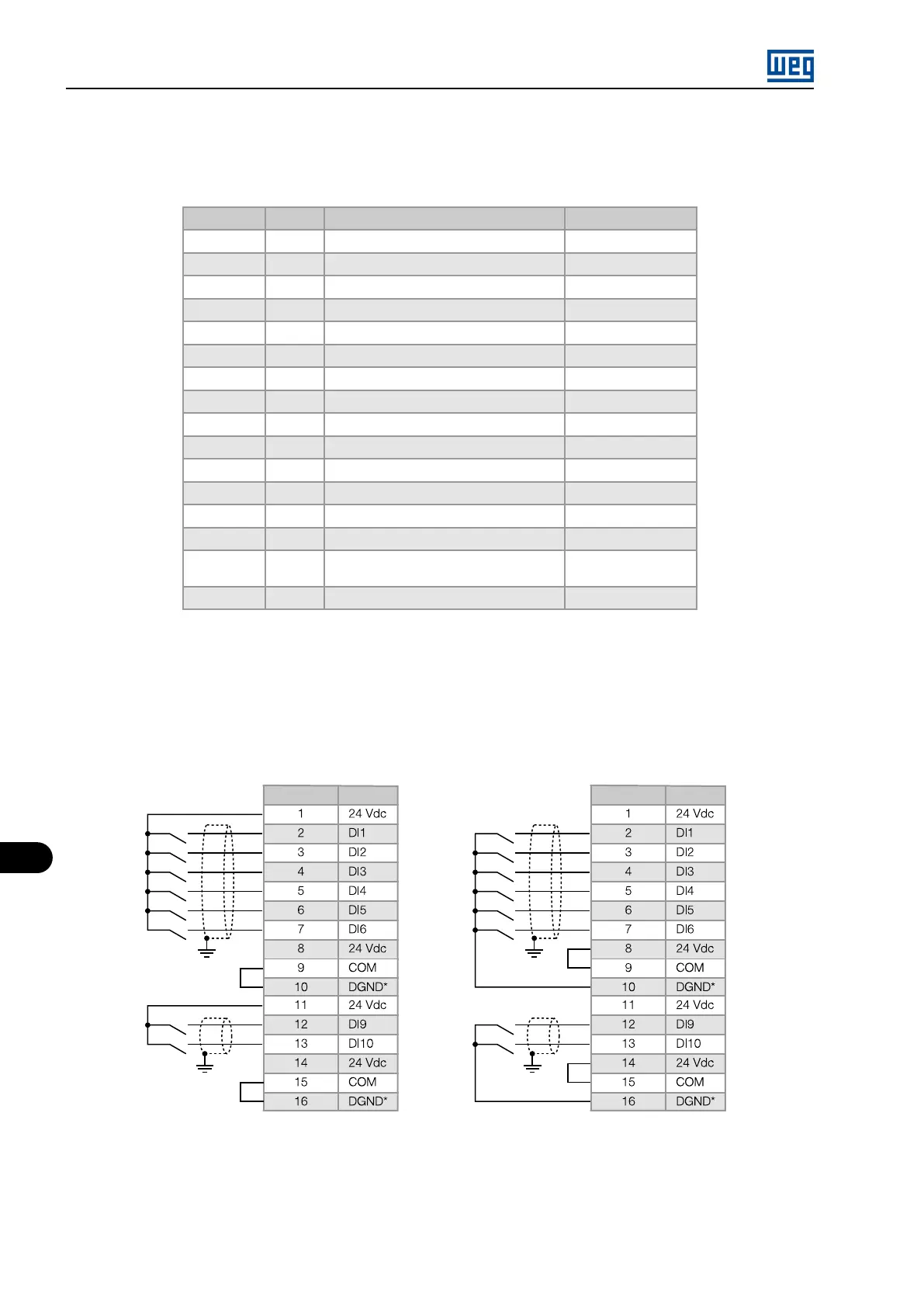
1 24 Vdc Power supply for digital inputs 24 Vdc ± 8%, 90 mA
2 DI1 P0263 = Run/Stop Isolated digital input
3 DI2 P0264 = FWD/REV Isolated digital input
4 DI3 P0265 = Not Used Isolated digital input
5 DI4 P0266 = Not Used Isolated digital input
6 DI5 P0267 = JOG Isolated digital input
7 DI6 P0268 = Ramp 2 Isolated digital input
8 24 Vdc Power supply for digital inputs 24 Vdc ± 8%, 90 mA
9 COM Common point of the digital inputs -
10 DGND* 0 V reference of the 24 Vdc power supply Grounded
11 24 Vdc Power supply for digital inputs 24 Vdc ± 8%, 90 mA
12 DI9 P0271 = Not Used Isolated digital input
13 DI10 P0272 = Not Used Isolated digital input
14 24 Vdc Power supply for digital inputs 24 Vdc ± 8%, 90 mA
15 COM Common point of the DI9 and DI10 digital
inputs
-
16 DGND* 0 V reference of the 24 Vdc power supply Grounded
NOTES:
- Isolated digital inputs
- Minimum high level: 18 Vdc
- Maximum low level: 3 Vdc
- Maximum voltage: 30 Vdc
- Input current: 11 mA @ 24 Vdc
Active low
Connector Signal
Active high
Connector Signal
Figure 11.2: Description of the XC1A connector: digital inputs
MVW01 | 11-2