6
MVW01 WC (WATER COOLED)
6.6 MECHANICAL DATA
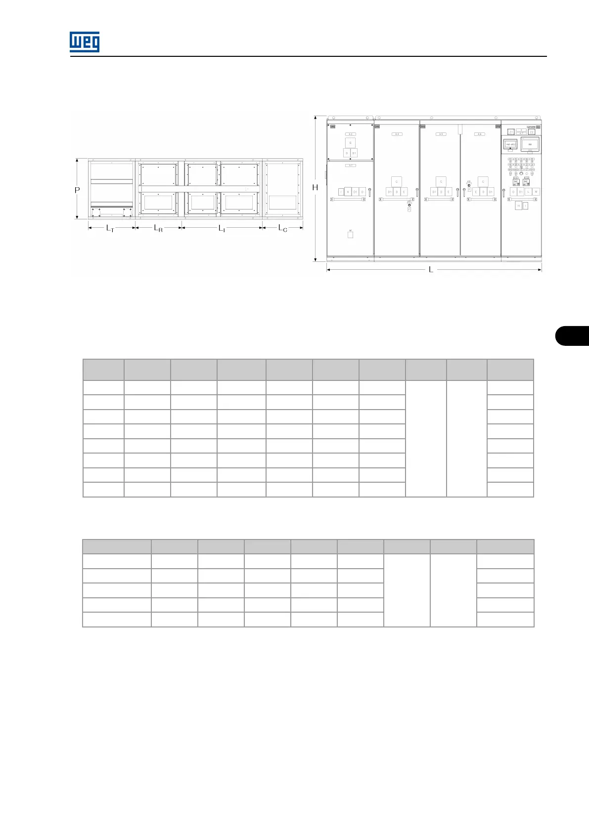
Figure 6.6: Panel Constructive Aspects
The MVW01 WC line is assembled in panels with the dimensions shown in Table 6.5 on page 6-9 and Table 6.6 on page 6-9 :
Table 6.5: Mechanical data 3L (dimensions in mm)
Frame
size
L
R
(mm) L
L
(mm) L
I
(mm) L
C
(mm) L
T
(mm) L (mm) H (mm) P (mm)
Weight
(kg)
AW
700 0 1200 600 700 3200
2200 1020
2500
CW
1200 2 x 600 2 x 1200 600 800 5700 4000
DW
1200 3 x 600 3 x 1200 600 1000 8000 5700
EW
1200 4 x 600 4 x 1200 600 1000 9800 6800
2 x DW
2 x 1200 6 x 600 6 x 1200 2 x 600 2 x 1000 2 x 8000 2 x 5700
2 x EW
2 x 1200 8 x 600 8 x 1200 2 x 600 2 x 1000 2 x 9800 2 x 6800
3 x DW
3 x 1200 9 x 600 9 x 1200 3 x 600 3 x 1000 3 x 8000 3 x 5700
3 x EW
3 x 1200 12 x 600 12 x 1200 3 x 600 3 x 1000 3 x 9800 3 x 6800
Table 6.6: Mechanical data 5L (dimensions in mm)
Frame size
L
R
(mm) L
I
(mm) L
C
(mm) L
T
(mm) L (mm) H (mm) P (mm)
Weight (kg)
C2W
1280 3 x 900 800 1280 6060
2200 1020
4800
C3W
1280 6 x 900 800 1280 8760 5200
3 x C2W
3 x 1280 9 x 900 3 x 800 3 x 1280 3 x 6060 3 x 4800
2 x C3W
2 x 1280 12 x 900 2 x 800 2 x 1280 2 x 8760 2 x 5200
3 x C3W
3 x 1280 18 x 900 3 x 800 3 x 1280 3 x 8760 3 x 5200
L
R
: Rectifier column. L
L
:Parallelism inductor column. L
I
: Inverter column. L
T
: Heat exchanger column. L
C
: Control column. H: Height. L:
Width. P: Depth.
Notes: Mechanical DW and EW with 18-pulse rectifier, consider + 800 mm of additional column for connections cable. For mechanics with
sinusoidal filter consult WEG. Tolerance for all dimensions ± 10 mm.
MVW01 | 6-9