2
GENERAL INFORMATION
2.3.3 MVW01 Electronic Boards
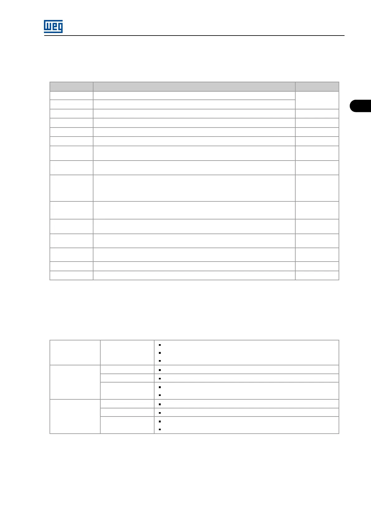
Table 2.9: MVW01 electronic boards
Name Function Panel / Module
MVC3 Main Control
Control/ A10
PIC2 Power supplies for the electronics, internal use digital inputs and output relays
MVC4 User interface control Control/ A12
FOI 3, 4 It converts electrical signals into optical signals and vice versa Control/ A8
EBA, EBB, EBC Optional function expansion boards Control/ A13
Fieldbus Optional network communication boards Control/ A14
ISOY/ISOZ Signal feedback boards, they measure medium voltages or temperatures and send the in-
formation via optical signals (1 channel)
Rectifier/ A9.3
ISOX Signal feedback boards, they measure medium voltages or temperatures and send the in-
formation via optical signals (2 channels)
Rectifier/ A9.1
A9.2
PS24
Electronics power supply:
Rectifier/ A11
- input: 220 Vca 3 ∼ or 220 Vca 1 ∼
- output: 24 Vcc
PS1/PS1S
Isolated power supply:
Control/ A2
- input: 22 Vca 1 ∼ (PS1)/220 Vca 1 ∼ (PS1S)
HVM It indicates that the DC link is energized (Neon lamps) Inverter (visible in
the control)
1SD210F2
1SP0335
Gate Drivers Inverter/ BIU,
BIV, BIW
PLC2 PLC expansion board - optional Control/
Rack A8
RSSI Absolute encoder interface - optional Control
HMI Cables
2.3.4 PLC2 Expansion Board
The PLC2 board presents the following hardware features:
Table 2.10: PLC2
COMMUNICATION Serial Interface
Rede CANopen Master/Slave and DeviceNet Slave.
Optional for Profibus DP Slave network.
Optional for rede DeviceNet Slave.
INPUT
Analog
1 differential analog input (-10 to +10) Vdc or (-20 to +20) mA, 14 bits.
Incremental Encoder
2 isolated encoder inputs, with external supply of 5 Vdc or (8 to 24) Vdc.
Digital
9 isolated digital inputs, bidirectional, 24 Vdc.
1 motor PTC input.
OUTPUT
Analog
2 analog outputs (-10 to +10) Vdc or (0 to 20) mA, 12 bits.
Serial Interface
1 serial communication interface - RS-232C (Standard protocol: MODBUS-RTU).
Digital
3 relay outputs: 250 V x 3 A.
3 optocoupled digital outputs, bidirectional, 24 Vdc x 500 mA.
MVW01 | 2-15