2
GENERAL INFORMATION
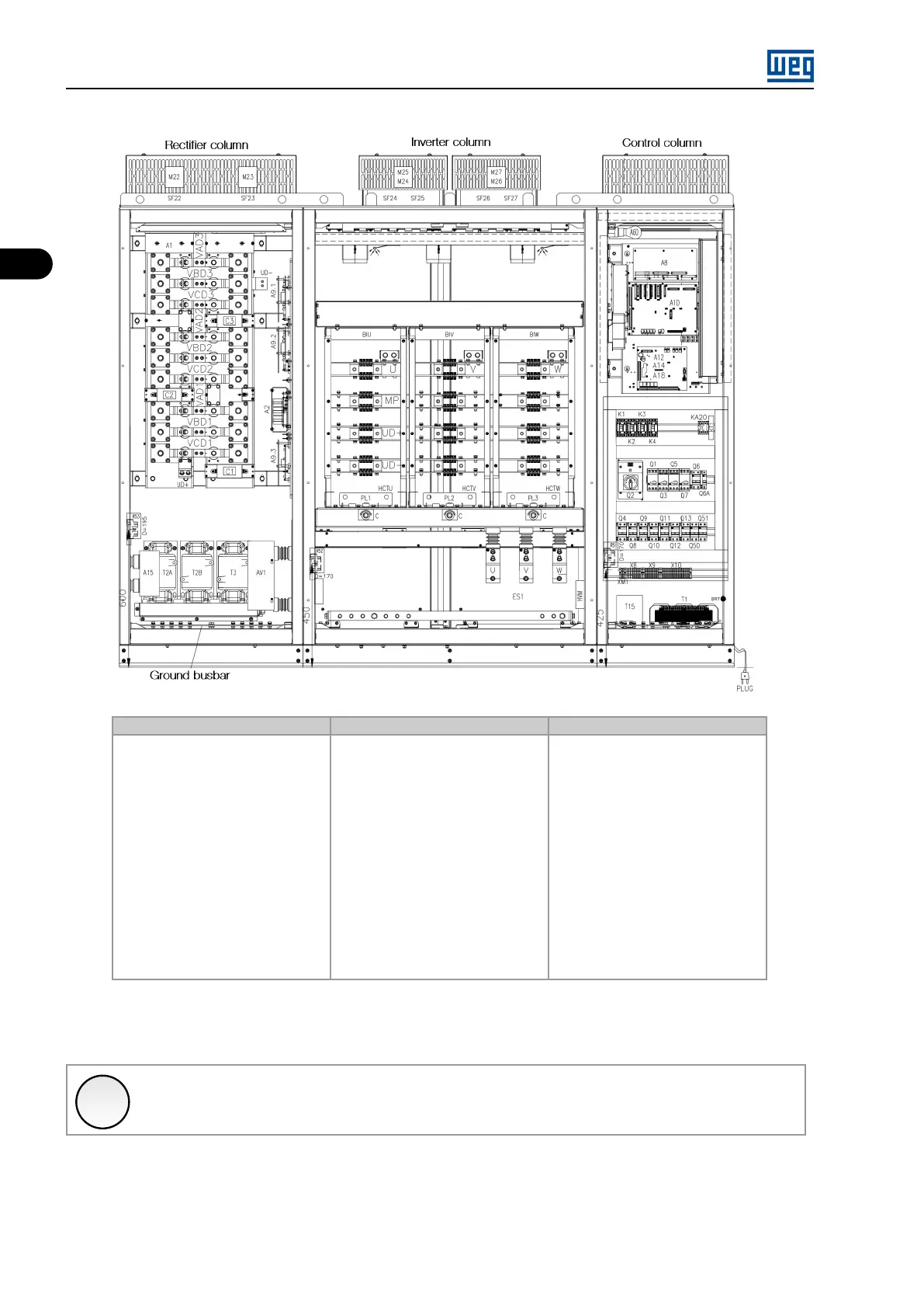
Rectifier column Inverter column Control column
The rectifier column receives the ca-
bles from the transformer through
the bottom of the cabinet. Besides
the power rectifier, this column also
contains electronic boards destined
to measurements and power sup-
ply, medium voltage pre-charge cir-
cuit, and medium voltage transform-
ers to supply these circuits. The cab-
inet has a grounding bar and its door
remains closed during the operation.
The measured signals are sent to the
control column via optical fibers.
The inverter column contains the in-
verter extractible arms (BIR, BIS and
BIT). Connection bars for the mo-
tor medium voltage cables are avail-
able, and are accessed via the cab-
inet bottom. The arm semiconduc-
tors are controlled and monitored
through fiber optic cables coming
from the control column. This col-
umn also contains the medium volt-
age Hall effect current transformers,
voltaic arc detection sensors and dif-
ferential pressure sensor probe used
to monitor exhausting fan faults. The
cabinet also has a grounding bar and
its door remains closed during the op-
eration.
The control column contains the elec-
tronic rack composed by the control,
fiber optics interface, power supply,
I/O, optional (function expansion and
communication network) boards, as
well as the command and protection
circuits destined to the system op-
eration (circuit breaker + transformer
+ inverter + motor), command trans-
former, low voltage pre-charge circuit,
Human Machine Interface and termi-
nal strips.
Figure 2.3: MVW01 G3 internal component arrangement (frame size A)
✓
NOTE!
For the Rectifier Panel, optionally the cables can entered through the top of the panel.
MVW01 | 2-14