11
OPTIONAL ACCESSORIES AND BOARDS
11.1.3 Relay output
Table 11.4: XC1A terminal strip description: relay outputs
Connector Relay Function (factory default) Specification
1 NA
2 RL1 C P0277 = No Fault 240 Vac, 1 A
3 NF
4 NA
5 RL2 C P0279 = N > Nx 240 Vac, 1 A
6 NF
7 NA
8 RL3 C P0280 = N* > Nx 240 Vac, 1 A
9 NF
10 NA
11 RL4 C P0281 = Not Used 240 Vac, 1 A
12 NF
13 NA
14 RL5 C P0282 = Not Used 240 Vac, 1 A
15 NF
16 - - - -
NOTES:
NF = normally closed contact.
NA = normally open contact.
C = common.
11.1.4 Wiring installation
In the installation of signal and control wiring, the following care must be taken:
1. Cable gauges 0.5 mm² to 1.5 mm².
2. Maximum torque: 0.50 N.m (4.50 lbf.in);
3. Connections to XC1A, XC1B and XC1C must be made with shielded cable and separated from the other connections (power, control
at 110/220 V, etc.). If those cables have to cross, such cross must be perpendicular, keeping a minimum separation distance of at least
5 cm at the crossing point;
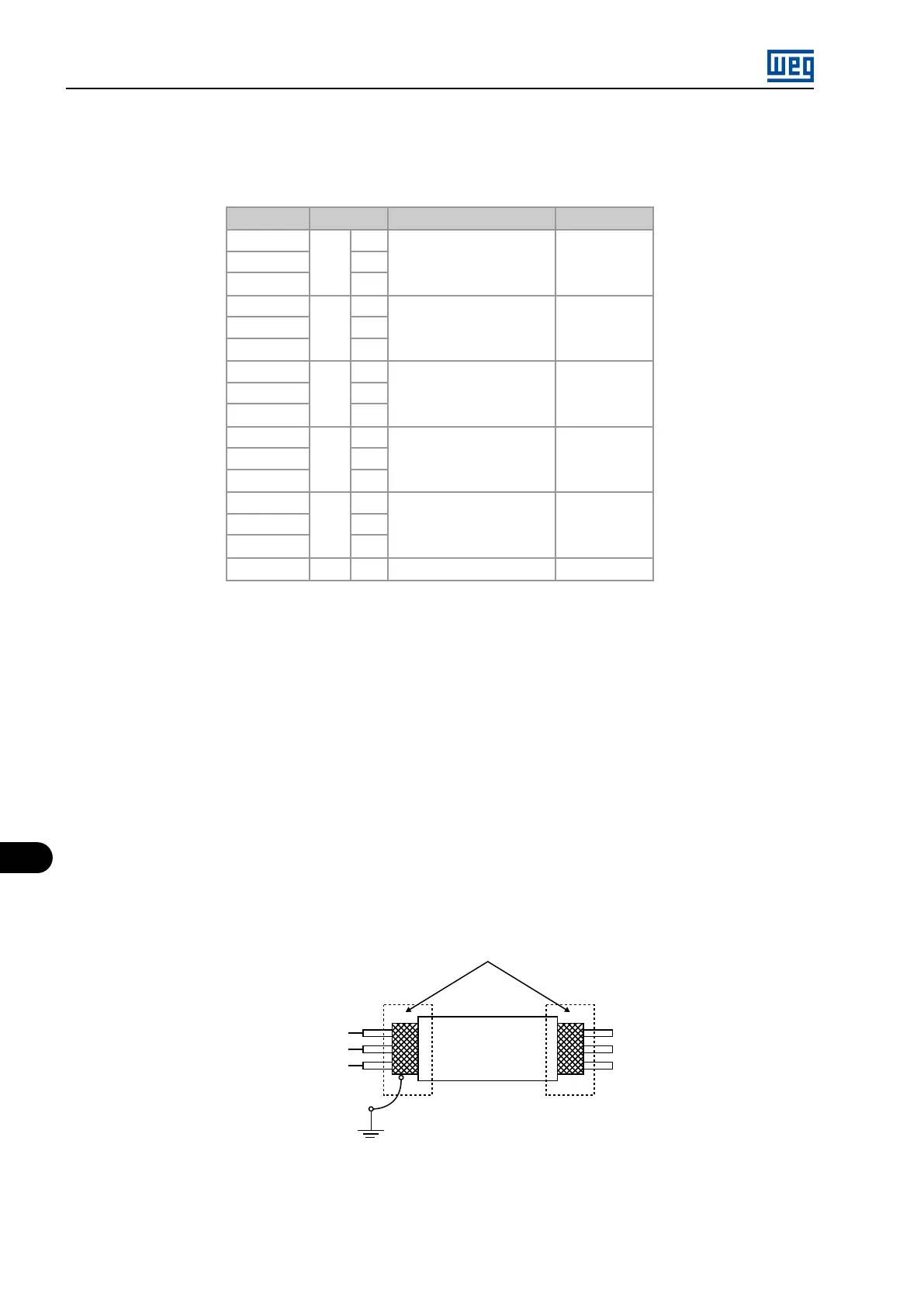
Screws located on the board and on the MVC4 board support plate, connect shield according to Figure 11.4 on page 11-4 :
Frequency
inverer
Connect to ground
Not grounded
Isolate with tape
Figure 11.4: Shield connection
4. It is necessary to use galvanic isolators at the XC1B terminal strip signals for wiring distances longer than 50 m (150 ft);
5. Relays, contactors, solenoids or electromagnetic braking coils installed near inverters can generate interference in the control circuit;
In order to eliminate this interference, connect RC suppressors in parallel with the coils of AC relays. Connect a free-wheeling diode in
case of DC relays/coils;
MVW01 | 11-4