6
MVW01 WC (WATER COOLED)
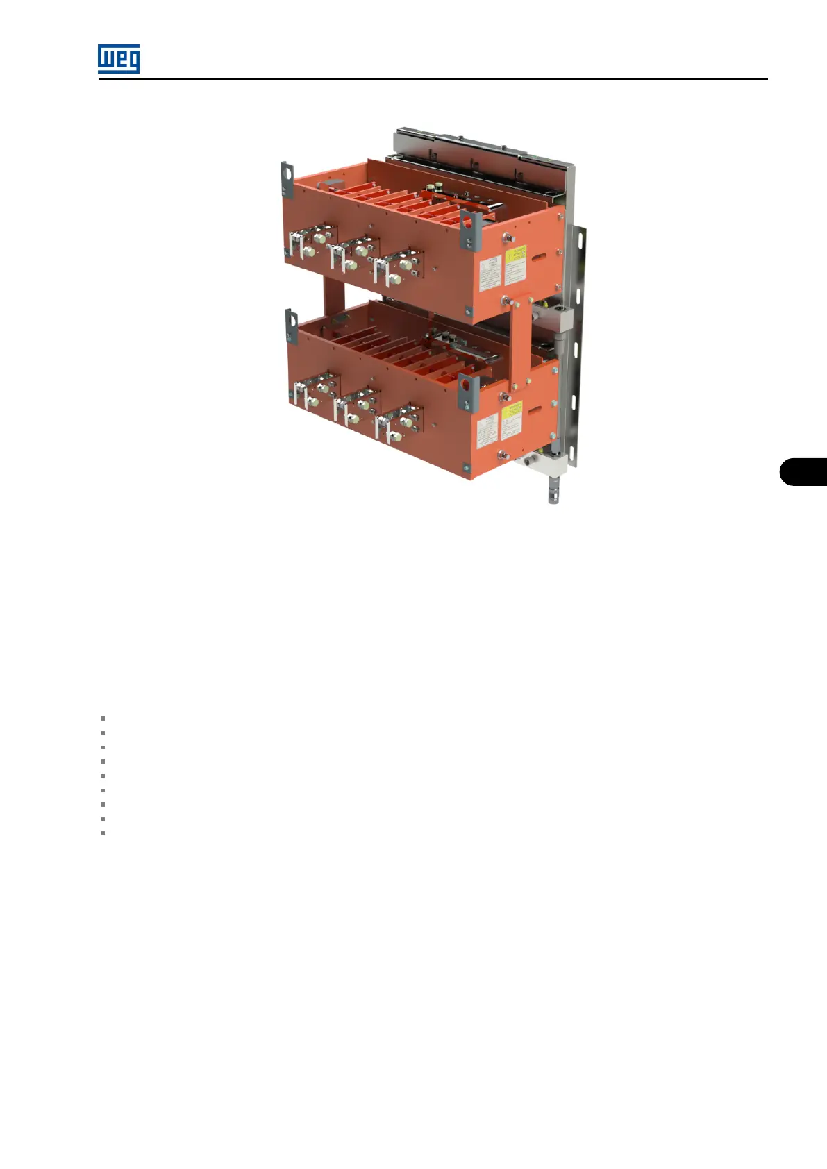
Figure 6.3: Water Cooled Rectifier 12 Pulse (example)
The rectifier is connected to the DC link located at the rear part of the MVW01 panel, in the inverter column. The DC bus supplies the voltage
for the inverter power arms.
6.2 MVW01 WC POWER ARMS
The inverter power arms contain:
04 medium voltage IGBT modules.
01 medium voltage diode module.
01 water cooled power heatsink.
01 flat busbar.
04 gate driver boards (one for each IGBT).
04 isolated DC/DC converters (gate driver board power supply).
01 heatsink temperature sensor (NTC thermistor).
01 ISOX.02 Signal Feedback Board.
01 NPC resistor.
The arm has mechanical structure formed by bulk molding compound (BMC) (polyester resin and fiberglass) and steel plates, chemically treated
to ensure resistance to corrosion.
The electric connection of the arms to the power busbars of the DC link is done by means of finger contacts located at the front of the capacitor
bank.
MVW01 | 6-3