8
INVERTER PARALLELISM
8 INVERTER PARALLELISM
The MVW-01 frequency inverter has a wide range of currents that comprise parallel arrangements of conventional models with the use of
reactors.
✓
NOTE!
A 5 % derating is applied to each parallel unit in order to compensate the power drop caused by the use of the reactor.
8.1 STRUCTURE OF THE PARALLEL INVERTER
Up to four inverters can be connected in parallel, by means of reactors, in order to extend the power range of the MVW01 line. In this manual
the standard inverter (not parallel) is identified as 3L, with two in parallel 3L2, with three in parallel 3L3, and with four in parallel 3L4.
The parameters and faults regarding the parallel inverter (3L2) suffered modifications in the arm nomenclature in order to adequate it to the new
6.9 kV inverter line and to the expansion of the existent 3300 V and 4160 V lines.
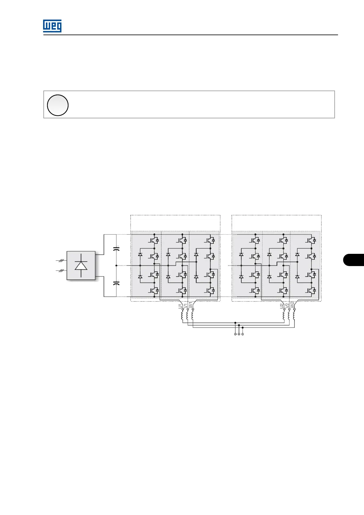
The figure below presents the power section structure of the inverter with the new HMI parameter correspondence.
Vcc+
(P0053)
Vcc-
(P0052)
V
(P0056)
U
(P0055)
W
(P0057)
VAp
(P0048)
UAp
(P0047)
WAp
(P0049)
Group A Group Ap
U V W
Temp. R1
(P0059)
Temp. R2
(P0051)
Figure 8.1: 3L2 line parameter correspondence
MVW01 | 8-1