12
SPECIAL FUNCTIONS
12.2 SYNCHRONOUS TRANSFER OR SYNCHRONOUS BYPASS FUNCTION
For applications where speed variation is not required during operation, the synchronous bypass function enables the motor to be accelerated
through the inverter up to the rated operating frequency, and then the transfer to the supply line to occur. In this way, it is possible to eliminate
the effects of the starting current related to a direct online start, and the frequency inverter is sized only for the motor starting condition.
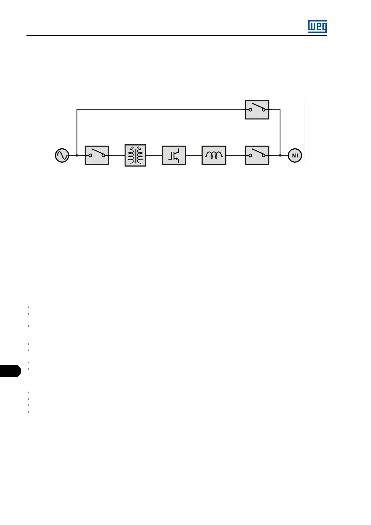
Line AC
Transformer MVW01
Bypass
Inverter
Input
reactor
cubicle
contactor
Line contactor
(Bypass)
Figure 12.4: General scheme of synchronous transfer
12.2.1 Basic Settings
The synchronous transfer process involves accelerating the motor up to the rated speed, synchronizing the voltage imposed to the motor with
the line voltage, and making the transfer to the line. For the transfer to occur properly and with minimal impact on the motor and on the inverter,
a series of parameters must be carefully adjusted so as to ensure the phase synchronization, the minimum difference of the RMS value between
the inverter and the line voltages and the timely occurrence of each step of the process.
Even with the correct setting of parameters related to the synchronous transfer process, it is necessary to use a reactor between the inverter
and the motor in order to absorb differences between the inverter and the line voltage, thus protecting the inverter during the closing of the line
contactor.
Therefore, after extract the bypass circuit breaker or contactor, making all the start-up procedure for inverter with operation in normal mode, it
is necessary to:
Configure the inverter in bypass mode (P0299 = 4).
Choose one of the DIs available on the MVC4 board (DI3 to DI10) and configure it to start the synchronous transfer (P0265 to P0272 =
23 or 25).
Configure the motor voltage (P0400 equal to the line voltage to which the motor will be transferred. In the operation with synchronous
bypass, the inverter uses this value to calculate the RMS voltage that will be imposed to the motor when operating at rated frequency.
E.g.: motor nameplate voltage of 4000 V and line of 4160 V. Configure P400 = 4160 V.
Start the motor at synchronous speed and close the digital input “Start Transf. Synchronous”.
Adjust the search regulator of the synchronous transfer (P0634 and P0635) to obtain a faster searcher or mitigate any oscillation in angular
error between the output voltage inverter and mains supply that prevents synchronization to happen.
Decrease the speed reference below 95% to exit the “Synchronism OK” state and repeat the procedure if necessary.
When the inverter indicates “Synchronism OK”, measure with the oscilloscope and compare the voltage generated by the inverter (PWM)
with the mains voltage (sinusoidal) for each of the phases. The inverter and grid voltages must be synchronized. The difference between
the grid and inverter phases can be non-zero, as long as it is constant. If the difference between the grid and inverter phases is different
from zero after synchronizing, adjust 0636.
Stop the motor.
Configure one DO (RL1 to RL5) to indicate that the synchronism with the line is “OK” (0277 to P0282 = 34).
Start the motor at synchronous speed and close the digital input “Start Transf. Synchronous”.
Set P0631 to compensate for the delay in closing the transfer breaker to the grid, so as to allow the inverter and grid to operate in parallel
for a maximum of 2 ms after the circuit breaker/contactor closes. The effect of a very long time on P0631 generates an increase in the
inverter current, which can reach the tripping value of the overcurrent fault F0070. In Sensorless mode, the inverter must be disabled
before opening the inverter output contactor/breaker.
MVW01 | 12-4