9
SUPPORTED MOTORS
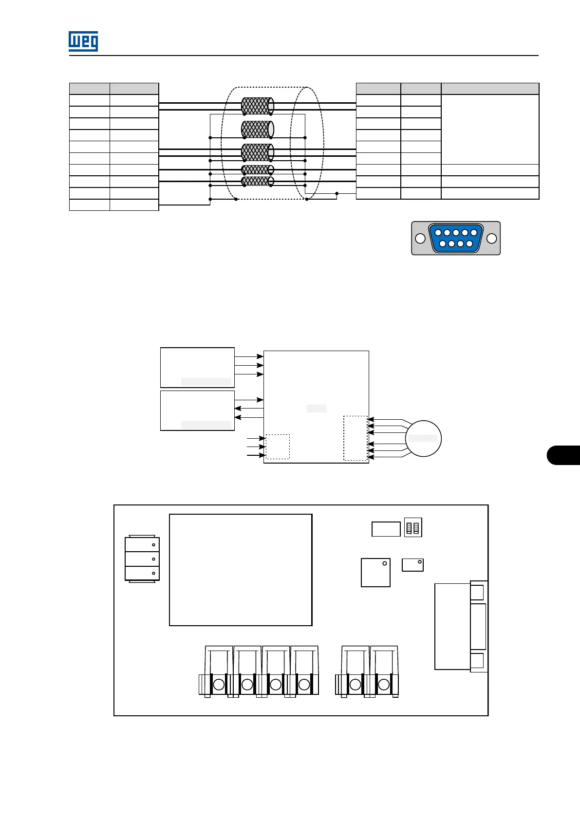
Signal
CLK +
CLK -
DATA +
DATA -
Vdc
DGND
Shield
{Cor}
Red
Blue
Yellow
Green
Gray
Pink
White
Brown
XC9
3
2
1
9
8
7
4
6
5
Description
Encoder
signals
Power supply
0 V reference
Ground
1 2 3 4 5
6 7 8 9
RSSI board
XC2 connector (Male DB9)
Signal
CLK +
CLK -
DATA +
DATA -
Vdc
DGND
Figure 9.3: RSSI - Encoder connection cable
The connections to the encoder and to the MVC3 boards and fiber optic interface board, and components of the RSSI board are shown in
Figure 9.4 on page 9-3 and Figure 9.5 on page 9-3 , respectively.
ND01-FOI3/FOI4/CIB
N3-FOI3/FOI4/CIB
N2-MVC3
MVW01 (A)
ND01-FOI3/FOI4/CIB
N3-FOI3/FOI4/CIB
N2-MVC3
MVW01 (B)
RDA
N3_CHA
N2_CHA
RDB
N3_CHB
N2_CHB
RSSI
XC1
XC2
1
2
3
Encoder
+24 V
Terra
GND
Figure 9.4: Connection diagram with the MVC3 and FOI3 boards
CTRL
XC1
-Vi (-Input)
+Vi (+Input)
Com (Common)
+5V (+Output)
-15V (-Aux)
Com (Common)
+15V (+Aux)
8
7
6
5
4
3
2
1
2 1
XC3
D1
B1
RSSI
XC2
21
1
2
3
S1
N3_CHA N2_CHA N3_CHB N2_CHB
RDB RDA
12119560 (GBR R02)
Figure 9.5: RSSI Board
MVW01 | 9-3
 Loading...


