9
SUPPORTED MOTORS
9.2.1.1 Absolute Encoder
The control of synchronous motors requires the use of an absolute encoder (available for the models shown in Table 9.1 on page 9-2 with 13
and 14 bits), which must observe the following specifications:
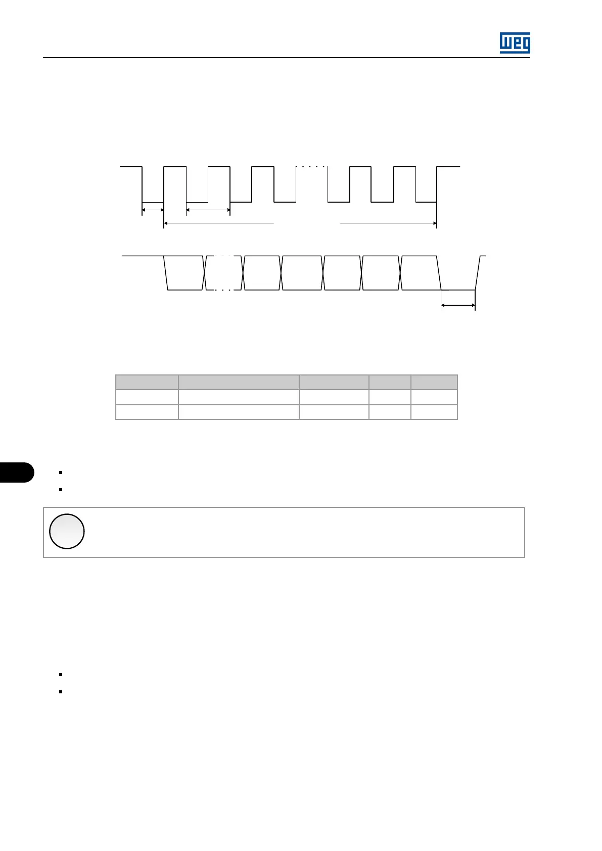
ParityZeroLSB
Bit 0 Zero Par.Bit 2Bit n
MSB
Clock
Date
t1 T
nT
t2
Bit 1
Figure 9.2: Example of Clock specification and data transfer to the absolute encoder
Table 9.1: Encoder recommendations for use in the MVW01
Manufacturer Encoder Model Quantity of bits Zero bit Parity bit
Leine Linde ISA647100150 13 Yes No
Baumer MHAP 400 B5 XXXXSB14EZ D 14 Yes Yes
When mounting the encoder next to the motor, it is recommended:
Coupling the encoder directly to the motor shaft (using a flexible coupling, however without torsional flexibility);
Both the encoder metallic housing and shaft must be electrically isolated from the motor (minimum spacing: 3 mm).
✓
NOTE!
The maximum encoder cable length is 200 m.
Refer to the motor project to define the type of encoder mounting.
Use good quality flexible couplings that avoid mechanical oscillations or backlash.
9.2.1.2 RSSI Board
The use of absolute encoder implies the need for an SSI data interface (Synchronous Serial Interface) between the encoder and the inverter.
The RSSI board was developed for the encoder specification previously described. This board needs to be powered with 24 V in direct current,
consumes up to 700 mA and has the following characteristics:
RS485 communication channel for data transmission and clock according to SSI standard with absolute encoder;
2 fiber optic communication channels for use with up to two MVC3 control boards and fiber optic interface board.
For electrical connection, use shielded cables, keeping them at least 25 cm away from the other cables (power, control etc.). Preferably, inside
a metallic conduit, as shown in Figure 9.3 on page 9-3 .
MVW01 | 9-2