10
INSTALLATION, CONNECTION AND ENERGIZATION
Table 10.2: Fiber optic cables identification
Fiber Optic
Arm
1
GS1x-N1-FOI x GS1
2
GS2x-N2-FOI x GS2
3
GS3x-N3-FOI x GS3
4
GS4x-N4-FOI x GS4
5
VST1x-N5-FOI x VST1
6
VST2x-N6-FOI x VST2
7
VST3x-N7-FOI x VST3
8
VST4x-N8-FOI x VST4
9
TEMPx-N9-FOI x TEMP
10
OSAx-N10-FOI x OSA
11
OSBx-N11-FOI x OSB
Table 10.3: Power arms supply cables identification
Cable Arm
1
BIX XC1
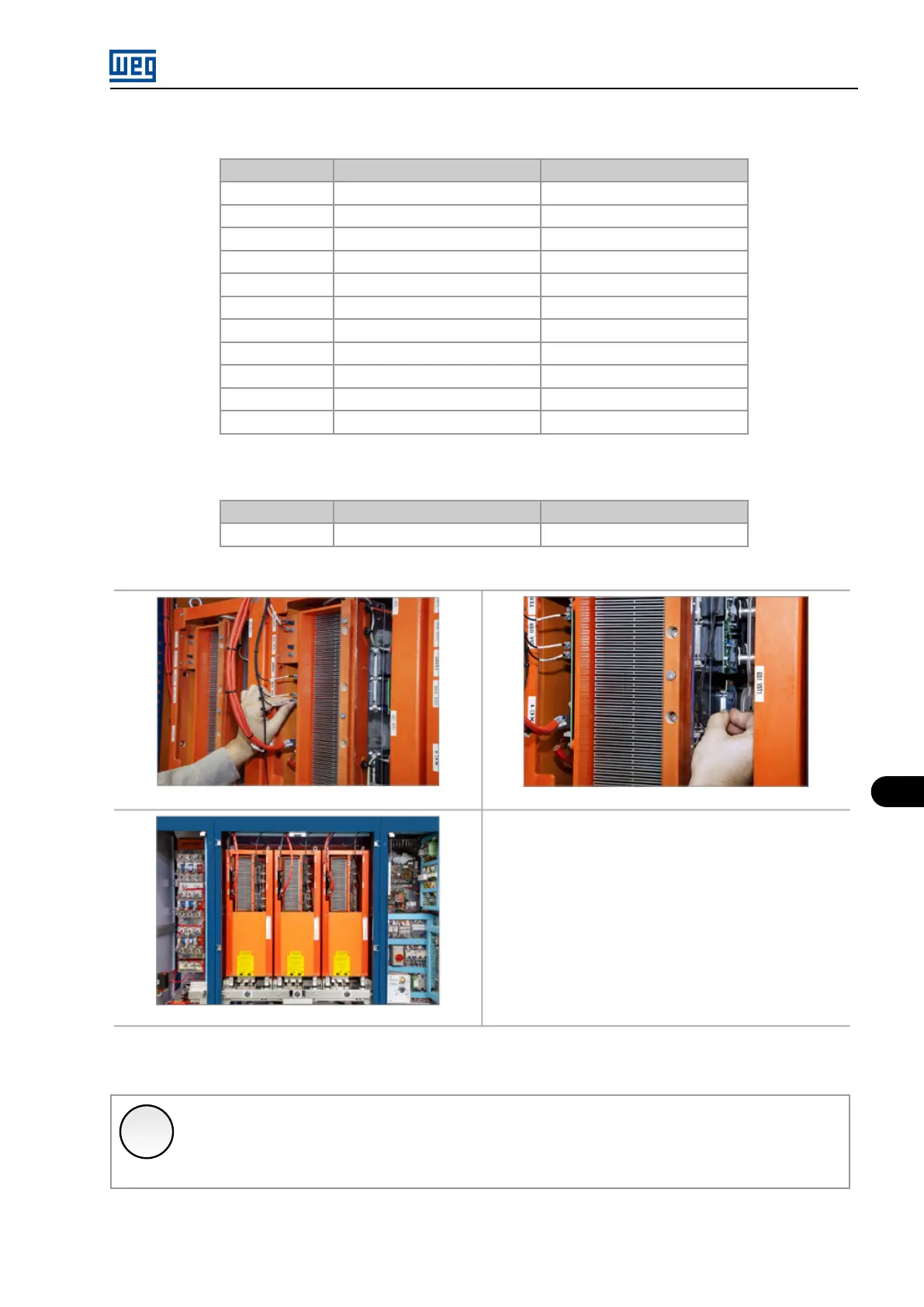
Figure 10.8: Details of the power arm supply and fiber optic cables installation stages
✓
NOTE!
The fiber optic cables must be handled with caution, in order not to fold, bend, squeeze or cut them.
Hold the cables only at their connectors when inserting or removing them, and never apply pressure or tensile force on the
fiber.
In order to extract the power arms follow the procedures described in the previous sections in reverse order.
MVW01 | 10-9