11
OPTIONAL ACCESSORIES AND BOARDS
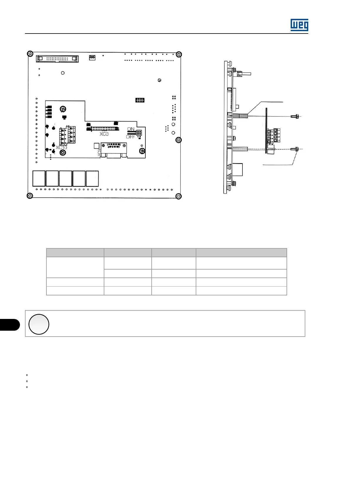
Screw M3 x 8
Torque 1Nm
Space material
10191668
Figure 11.18: Procedure to install the EBC1 board
CONFIGURATIONS:
Table 11.16: Configurations of the setting elements - EBB board
Expansion Board
Power supply Encoder Voltage
Necessary Setting
EBC1.01
External 5 V 5 V
Switch S8 to ON, consult Figure 11.16
on page 11-17 for more details
External 8 V to 15 V 8 V to 15 V
No action
EBC1.02
Internal 5 V 5 V
No action
EBC1.03
Internal 12 V 12 V
No action
✓
NOTE!
The XC10:22 and XC10:23 terminals (see Figure 11.16 on page 11-17 ) should only be used to power the encoder if the
connection to the DB9 connector is not used.
ENCODER MOUNTING:
Follow the recommendations bellow when mounting the encoder on the motor:
Coupling the encoder directly to the motor shaft (using a flexible coupling, however without torsional flexibility);
Both the shaft and the metallic frame of the encoder must be electrically isolated from the motor (minimum distance of 3 mm);
Use good quality flexible couplings that prevent mechanical oscillations or “backlash”.
Use shielded cable for the electrical connection, keeping it as far as possible (> 25 cm) from the other wiring (power, control, etc.). Preferably,
inside a metallic conduit.
During start-up, it is necessary to program parameter P0202 (Control Type) = 4 (Encoder) to operate with speed feedback by incremental
encoder.
For further details on vector control, see the programming manual available for download on www.weg.net.
MVW01 | 11-18