11
OPTIONAL ACCESSORIES AND BOARDS
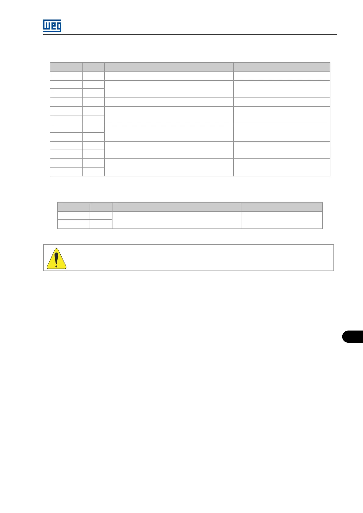
Table 11.17: XC9 terminal strip connections
Connector Signal
Function (Factory default)
Specification
1 +5.4 V
Positive reference for potentiometer
+5.4 V +-5 %, 2 mA
2 AI1-
P0740 (AI1 MVC3 Funct.): 0 (Not Used)
Differential, 11-bit resolution
3 AI1+ Impedance: 400 kΩ (-10 V to 10 V)
4 -4.7 V
Negative reference for potentiometer
-4.7 V +-5 %, 2 mA
5 AO1+
P0652 (MVC3 AO1 Funct.): 2 (Current Iu)
Differential, 11-bit resolution
6 AGND -10 V to 10 V, RL ≥ 10 kΩ (Maximum load)
7 AO2+
P0654 (MVC3 AO2 Funct.): 5 (g_usM)
Differential, 11-bit resolution
8 AGND -10 V to 10 V, RL ≥ 10 kΩ (Maximum load)
9 AO3+
P0656 (MVC3 AO3 Funct.): 2 (Current Iu)
Differential, 11-bit resolution
10 AGND -10 V to 10 V, RL ≥ 10 kΩ (Maximum load)
11 AO4+
P0658 (MVC3 AO4 Funct.): 5 (g_usM)
Differential, 11-bit resolution
12 AGND -10 V to 10 V, RL ≥ 10 kΩ (Maximum load)
Table 11.18: Description of the XC1 connector
Connector Signal
Function (Factory default)
Specification
1 AI2-
P0744 (AI2 MVC3 Funct.): 0 (Not Used)
Differential, 11-bit resolution
2 AI2+ Impedance: 400 kΩ (-10 V to 10 V)
WARNING!
The I/Os described above are not isolated. Their utilization must be with galvanic isolators.
MVW01 | 11-21