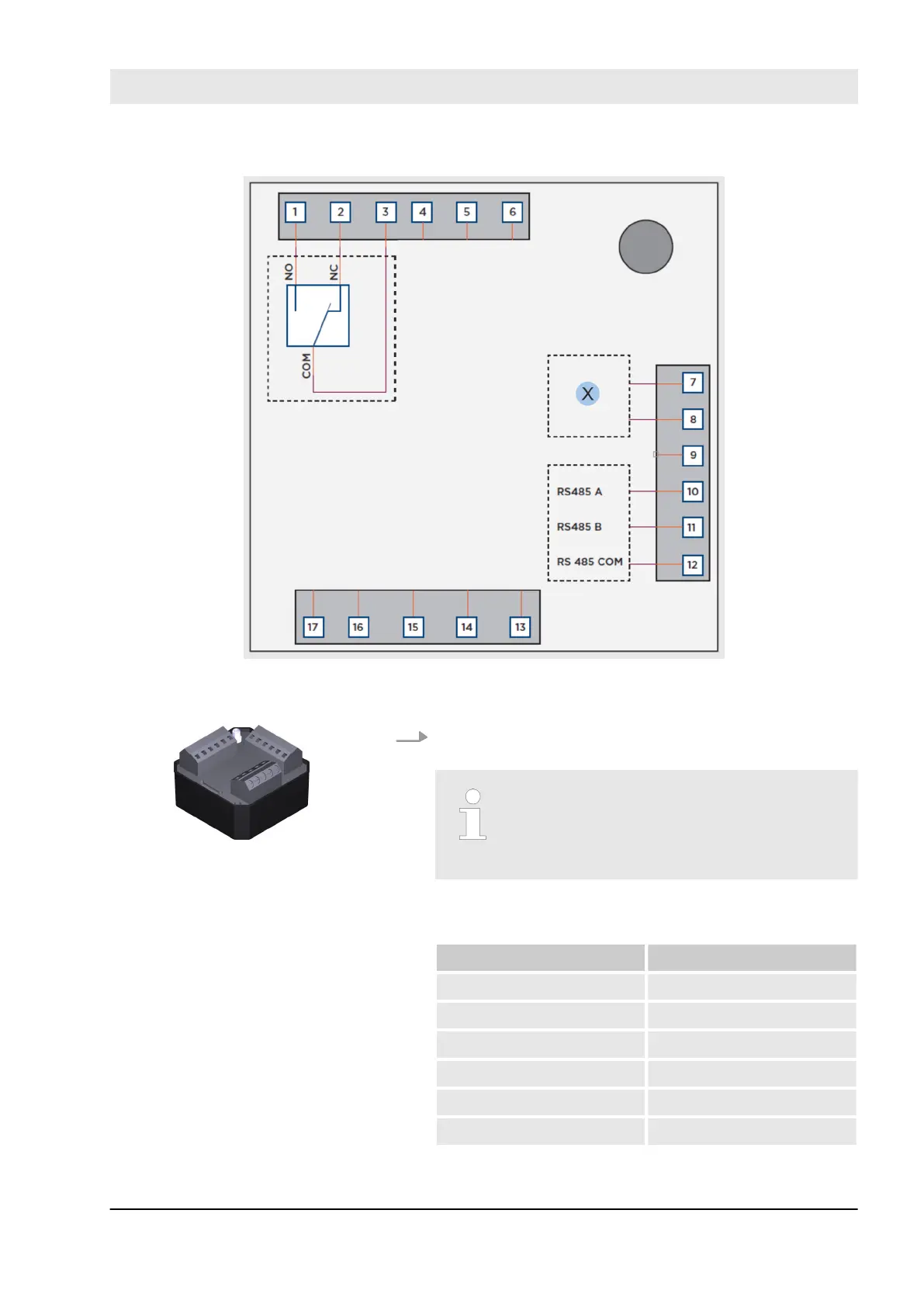
Fig. 51: Terminal assignment on the control unit
X Voltage
15. Use a circuit diagram for wiring the control unit inter-
nally.
Wiring the terminals on the control unit
Terminals 4, 5, 6 and 13 to 17 are not
used on the blueCompact reader and
must not be wired!
The table provides an overview of the wiring of the
terminals:
Terminal Assignment
1 Relay NO
2 Relay NC
3 Relay COM
4 – 6 -
7 V1
8 V2
Fig. 52: Control unit
Select and install reader
23.03.2020 blueCompact electronic locking system 73