WPC 1000 User Manual 1125100
Initialization, Setup, and Checkout 3-9
EXAMPLE
If the displayed Top-stop “On” Angle is 287°, you would calculate as follows:
360° - 287° = 73°
211° + 73° = 284°
You would set your Top-stop “On” Angle to 284°.
9. Select the “Top Stop Angle” indicator, and set the Top-stop “On” Angle to the value you
calculated in step 8.
10. Save the new Top-stop “On” Angle setting by pressing the Reset/Select button until the
“Angle/SPM” indicator is lit.
11. Determine the angle at which to install the overrun sensor magnet, referring to Table 3-3,
below.
First, locate the cell in the “Top-stop Angle” row displaying the range of angles within
which your calculated Top-stop “On” Angle falls; then, move down one row in that
column to find the mounting angle for the overrun sensor magnet. If you wish, you can
use the “Your Settings” column in the second row to record the correct mounting angle.
Example
You calculated in step 8 that your Top-stop “On” Angle is 284°, which falls in the 271° to
300° column in Table 3-3. The correct mounting angle for the overrun sensor magnet would
be 330°. See Figure 3-5, page 3-10.
WHEN DETERMINING TOP-STOP “ON” ANGLE
Remember that the Top-stop angle has an internal dwell of 20°. The internal Top-stop
timing turns off 20° after the Top-stop angle that you set. This internal Top-stop timing
must turn off before the overrun limit switch turns on. If the Top-stop timing and the
overrun limit switch are “on” simultaneously, an “80 series” error code will display (see
Top-stop and Overrun Setting Faults, page 5-16).
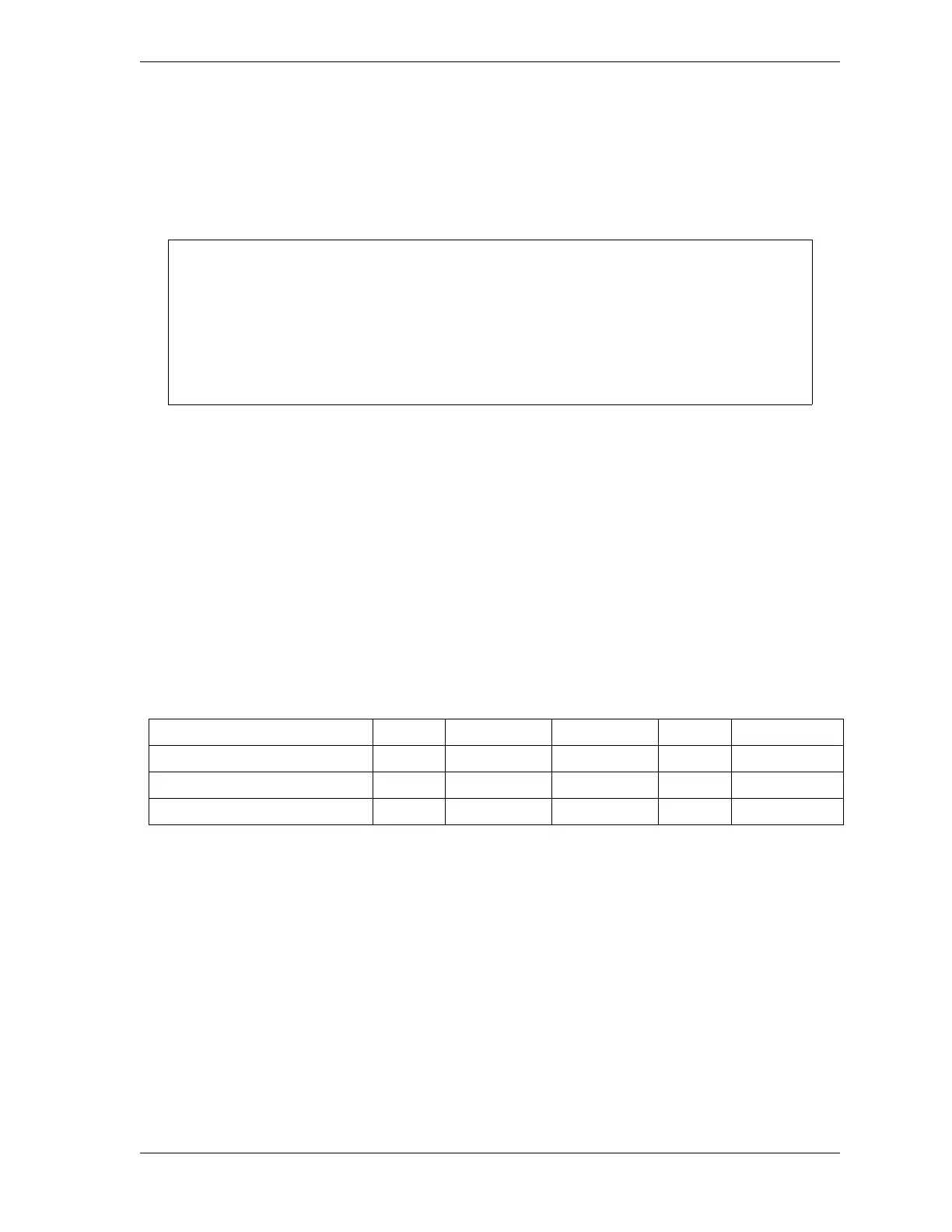
Table 3-3. Overrun Sensor Magnet Location and Option Switch Settings
Top-stop Angle
< 240° 241° to 270° 271° to 300° > 301° Your Settings
Magnet Mounting Angle
270° 300° 330° 359°
Switch 1 Setting
ON ON OFF OFF
Switch 2 Setting
ON OFF ON OFF

 Loading...