1125100 WPC 1000 User Manual
3-36 Initialization, Setup, and Checkout
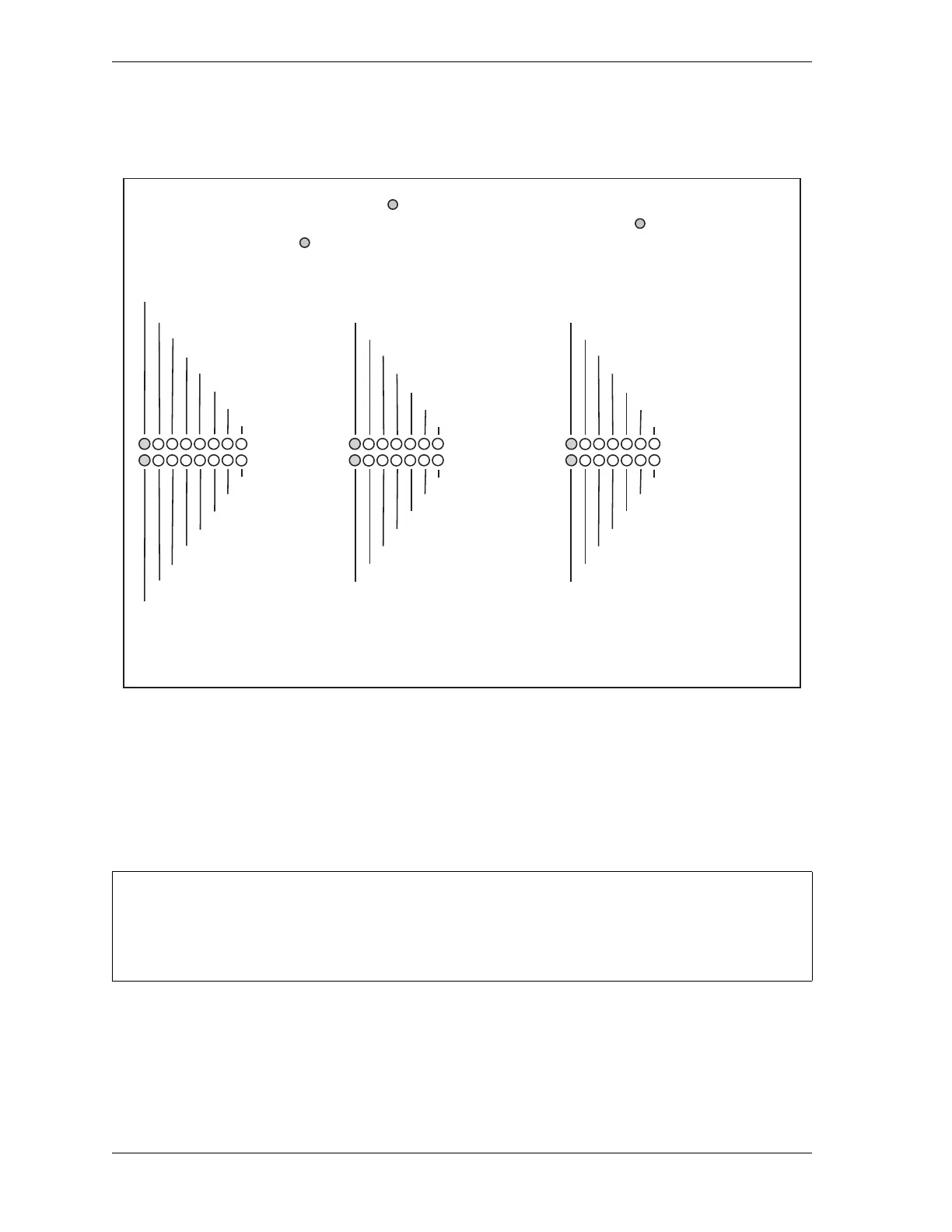
Many of the tests ask you to check the state of LEDs on the WPC 1000 Control board. An
LED map, showing the locations of all LEDs, is provided in Figure 3-14.
In order to run the tests, you need to know how to operate the press in Inch, Single-stroke, and
Continuous modes using Two-hand, One-hand, or Foot control. Refer to the instructions
starting on page 4-7 if you need help running the press using these settings.
Checking the Emergency-stop Circuit
To check the Emergency-stop circuit, do the following:
1. Run the press in Continuous mode, and press the Emergency Stop button on the Operator
Station. The press should Emergency-stop immediately.
Figure 3-14. WPC 1000 LED Indicator Map
CHECKING THE EMERGENCY-STOP CIRCUIT IN SINGLE STROKE MODE
If your press does not run in Continuous mode, run this test while the press is making a stroke in
Single-stroke mode.
All LEDs are red except ones that are shaded, which are green. LEDs for each group
are identified by number. Corresponding pin numbers for LEDs are shown in bold.
LEDs w/out pin numbers are for internal connections. Pins 141-157 are on display board.
+ 24 VDC
+ 5 Logic A
+ 5 Logic B
GROUP 1
144 - Inch select
145 - Off select
142 - Continuous select
148 - Foot select
143 - Single-stroke select
149 - One-hand select
Up button
Reset button
3 64 7 8512
GROUP 2
2 - Palm switch input N/O +
3- Foot switch input N/O +
4 - One-hand input +
6 - User input 3B -
5 - Prior act input +
7 - Overrun limit sw. input -
8 - Light curtain input 1 -
29 - E-Stop input 1 +
3 64 7 8512
GROUP 3
157 - Micro-inch select
Down button
156 - Top stop in inch select
18 - Motor reverse input +
19 - Remote reset input -
20 - User input 3A -
21 - Light curtain input 2 -
3 64 7512
GROUP 4
30 - Top stop input 1 +
31- Bar selector switch input +
32 - Motor forward input +
16 - Foot switch input N/C +
15 - User input 2 +
17 - Bar actuator input +
41 - Top stop input 2 +
3 64 7512
GROUP 5
Lockout contact check
DSV A contact check
Lockout drive check
DSV A drive check
DSV B contact check
DSV B drive check
Mute lamp 2 check
3 64 7512
GROUP 6
42 - E-stop input 2 +
44 -
DSV monitor input +
45 - User input 1 (Carryup limit sw.) +
46 - Palm switch input N/C +
22 - Clutch air pressure sw. input -
Mute lamp 1 check
Display w/ counter present
3 64 7512

 Loading...