1125100 WPC 1000 User Manual
3-10 Initialization, Setup, and Checkout
12. Determine the option switch 1 and 2 settings required for your calculated Top-stop “On”
Angle, referring to Table 3-3. WPC 1000 uses these settings to determine at what angle to
begin the overrun sensor closure test, which is used to make sure that the overrun limit
switch closes at the same angle on every stroke.
Move down from the cell in which the correct magnet mounting angle falls (see step 11) to
find the correct switch settings in last two rows of the table. If you wish, you can use the
“Your Settings” column in those rows to record those settings.
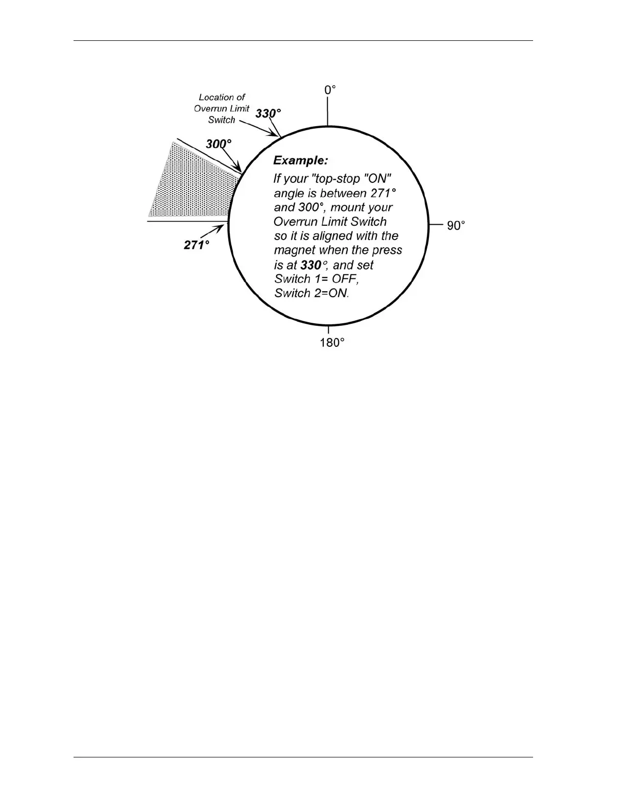
Example
You calculated in step 8 that your Top-stop “On” Angle is 284°, which falls in the 271° to
300° column in Table 3-3. The correct switch settings would be OFF for switch 1 and ON
for switch 2. See Figure 3-5.
13. Set option switches 1 and 2 on S101 on the WPC 1000 Control board to the positions you
determined in step 12, referring to Switches 1 and 2 – Top-stop “On” Angle Range,
page 3-27 for instructions.
14. If you are using the Auto Compensated Top Stop feature, return switch 4 on S101 to its
ON setting to enable it (see step 1).
15. Power down, then power back up the WPC 1000 to enable the new option switch settings.
Figure 3-5. Setting Overrun Timing: Example

 Loading...