1125100 WPC 1000 User Manual
2-36 Installation
6. Run the twelve-conductor cable through flexible, liquid-tight conduit to the terminal
points at the cam output assembly. You can use the knockouts directly below the
connectors if you have the cam output enclosure.
7. Remove the TB1 connector from the Cam Output board, and attach the wires at the other
end of the cable to the terminals shown in Table 2-9 and Figure 2. If you ordered the
enclosure, a wire from the CHAS terminal (pin #1) to a lug on the enclosure should
already be connected. Plug the connector back into its socket when you are finished.
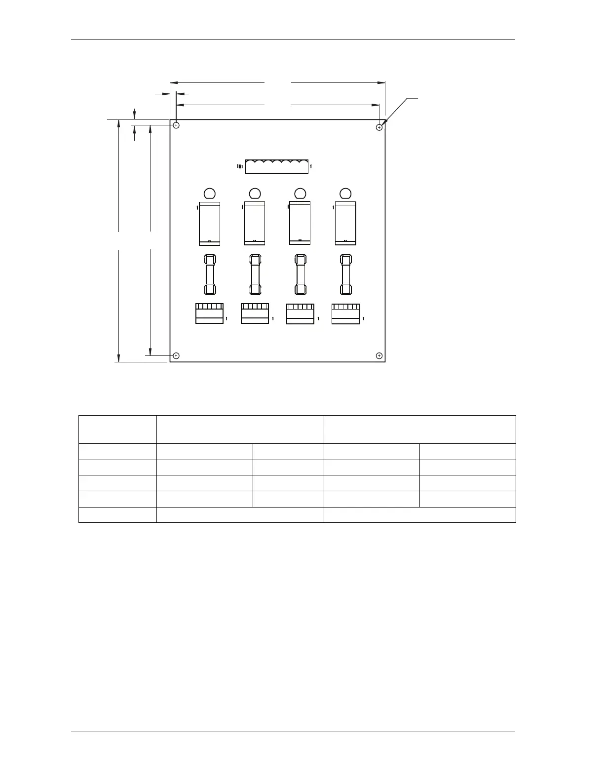
Figure 2-18. Cam Output Board: Mounting Dimensions
Table 2-9. WPC 1000 Control Board to Cam Output Assembly (TB1) Wiring Connections
Wire Color WPC 1000 Control Board
Pin # Signal
2-channel Cam I/O Assembly (TB1)
Pin # Signal
48 (TB102-Bottom) + 24 Vdc 2 + 24 Vdc
23 (TB102-Top) Ground 3 Ground
34 (TB101-Bottom) Cam 2 6 Channel 2
33 (TB101-Bottom) Cam 1 7 Channel 1
Terminate drain wire to ground stud Terminate drain wire to ground stud
DS1 DS2 DS3 DS4
K1
F1
K2
F2
K3
F3
K4
F4
N/O
C
N/C
N/O
C
N/C
N/O
C
N/C
N/O
C
N/C
CHAN 1 CHAN 2
TB3TB2
CHAN 3 CHAN 4
TB4 TB5
CHASSIS
+24V
GND
CH 3
CH 2
CH 1
CH 4
5A 125 VAC
SLO-BLO
5A 125 VAC
SLO-BLO
5A 125 VAC
SLO-BLO
5A 125 VAC
SLO-BLO
4.35
(110.5)
4.75
(120.7)
5.50
(139.7)
5.10
(129.5)
0.20 (5.1) TYP
0.20
(5.1)
TYP
clearance hole
for #6 screw
4 PLACES
Dimensions: inches
(mm)

 Loading...