WPC 1000 User Manual 1125100
Initialization, Setup, and Checkout 3-11
Mounting the Overrun Sensor Magnet
To mount the overrun sensor magnet, perform the following steps:
1. With the press in Inch mode, press the Run/Inch palm buttons until you have inched the
press to the overrun sensor magnet position you determined in step 11 of the previous
procedure.
2. Using double-sided foam tape or other means, temporarily install the magnet directly
beneath the overrun sensor, referring to Mounting the Overrun Sensor Switch, page 2-26.
3. Check to make sure that the “Overrun Limit Switch input” LED (#6) in LED Group 2 on
the WPC 1000 Control board is lit, referring to the LED map in Figure 3-14, page 3-36 for
location. This LED illuminates when the overrun magnetic switch senses the magnet.
4. Run the press in Inch mode for about 4 strokes, viewing the overrun sensor’s On/Off
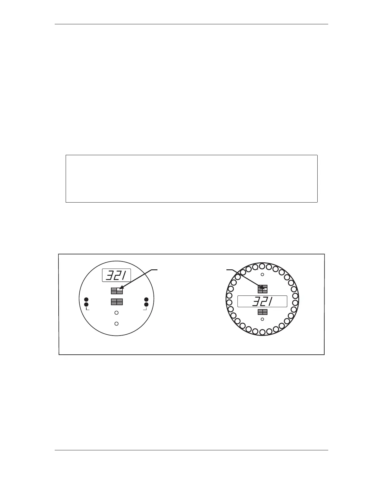
angles on each stroke. To display the On/Off angles, press the Reset/Select button until
the “Stopping Time” indicator is illuminated, then turn the WPC Settings key switch to
“+” to view the “on” angle and to “–” to view the “off” angle (see Figure 3-6).
Example
If you mounted the magnet at an angle of 330°, the magnetic switch might come “on” at,
say, 321°, and go “off” at 337°.
5. Run the press in Inch, Single-stroke, and Continuous modes for about 4 strokes each.
If the press cycles in every mode without a fault, go to step 6.
If a fault occurs while you are cycling the press in one or more modes, do the following:
Make sure that the overrun limit switch has enough dwell to provide an adequate signal at
high speeds. Optimally, the magnet should actuate the switch for 15° to 25°. The larger
the diameter of the shaft on which the magnet is mounted, the shorter the dwell (see
Figure 2-14, page 2-26). The ideal shaft diameter is 4 to 6 in.
Figure 3-6. WPC 1000 Displays Showing Overrun Sensor “On” Angle
With Stopping Time segment
selected, turn WPC Settings
key switch to + to view
overrun on angle and
to - to view overrun
off angle
BRAKE WARNING
INTERRUPTED STROKE
TOP STOP ANGLE
AUTO CARRYUP
STOP TIME LIMIT
MICRO-INCH
STOPPING TIME
STOPPING ANGLE
90
° STOP TEST
COUNTER
COUNTER PRESET
ANGLE / SPM
INTERRUPTED STROKE
BRAKE WARNING
TOP STOP ANGLE
AUTO CARRYUP
ANGLE / SPM
90° STOP TEST
STOP TIME LIMIT
MICRO-INCH
STOPPING TIME
STOPPING ANGLE
WPC 1000 Standard Display WPC 1000 Optional Counter Display
CAM 2
off
on
CAM 1
on
off

 Loading...