WPC 1000 User Manual 1125100
Installation 2-53
8. Install the Reset/Select button in the left cutout below the display. Wiring for the Reset/
Select button is provided on the Settings key switch wiring harness (see step 10).
9. Install the Mute lamp in the center cutout. The Mute lamp includes wiring and a
connector for attachment to the WPC 1000 Display board.
10. Install the Settings key switch in the right cutout. The Settings key switch includes a
wiring harness with connectors for attachment to the Reset/Select button and the WPC
1000 Display board.
11. Slide the connector at the end of the yellow wire on one arm of the Settings key switch
wiring harness over the topmost terminal on the switch body of the Reset/Select button, as
shown in Figure 2-30, page 2-54.
Slide the connector at the end of the two black wires on the same arm of the wiring
harness over the lower terminal on the Reset/Select button switch body, as shown in
Figure 2-30.
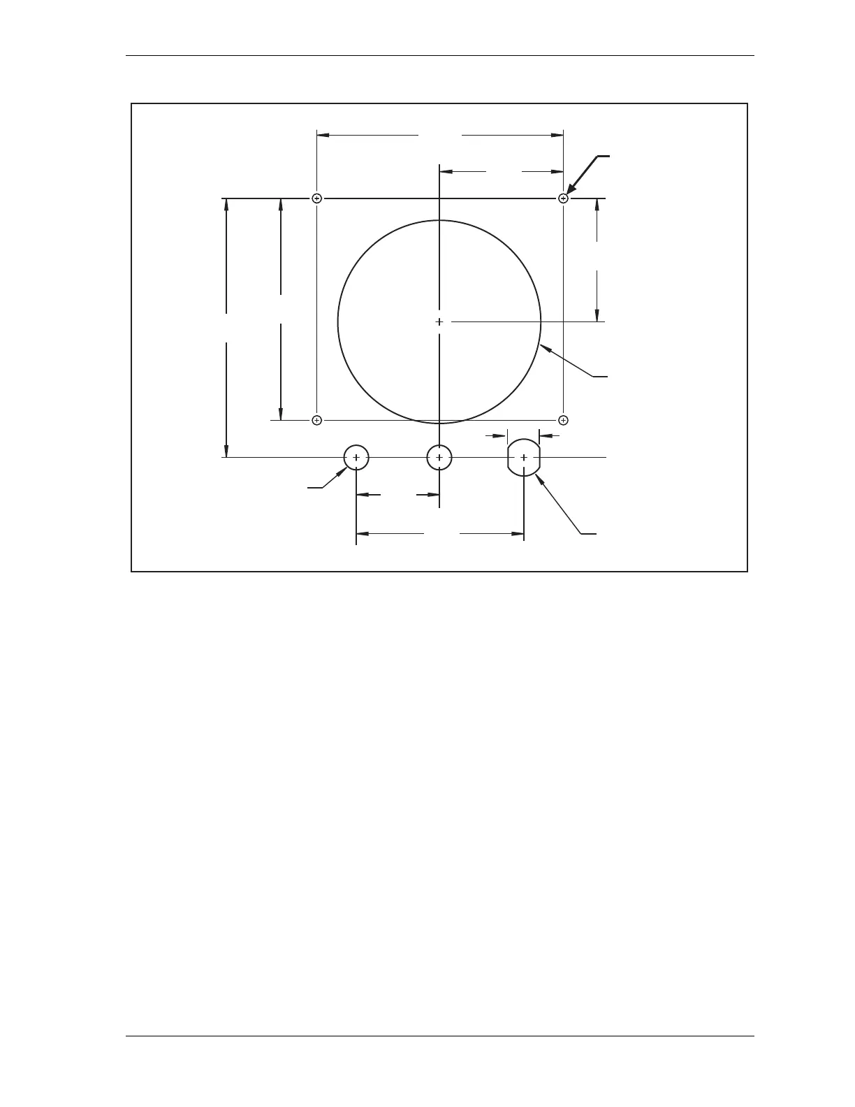
Figure 2-29. WPC 1000 Display Board Kit: Mounting and Cutout Dimensions
Dimensions:
inches (mm)
2.500
(63.5)
5.000
(127.0)
0.500 (12.7) DIA.
2 places
0.64 (16.3)
4.12
(104.6)
4.500
(114.3)
5.235
(133.0)
3.400
(86.4)
0.76 (19.3)
1.700
(43.2)
6-32 x 0.625 studs
(on far side)
4 places
2.500
(63.5)
DIA.
DIA.

 Loading...