WPC 1000 User Manual 1125100
Installation 2-65
22. Plug the completed ribbon cable connector assembly into J706 on the WPC 1000 Display
board (see Figure 2-16, page 2-33). The connector must be inserted with the same
orientation as the connector you plugged into J104 on the WPC 1000 Control board in
step 3.
23. Connect the ring lug on the end of the insulated shield (see Figure 2-39) to the standoff
beneath J706, using the hex nut that secures the board to the standoff.
Installation Verification
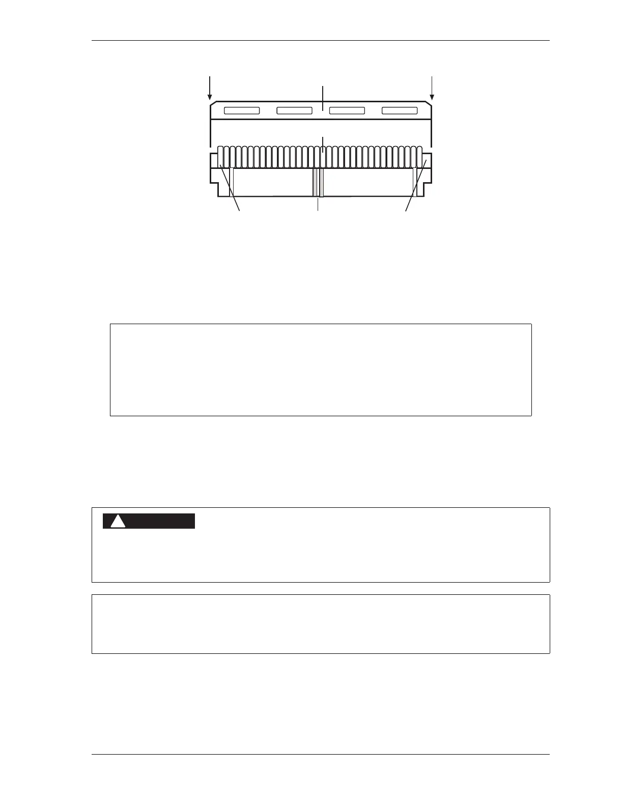
Figure 2-44. Strain Relief Installed on Connector (Gray Conductors)
The ribbon cable connector can be plugged into the J706 connector in only one direction.
When inserting the plug, make sure to align the key in the plug with the middle groove on
the J706 connector. The end of the ribbon cable connector with the red wire must be
positioned at the end of J706 labelled “1.” If the plug is not inserted correctly, the display
will not work properly.
PERFORM INSTALLATION VERIFICATION BEFORE OPERATING PRESS
Complete Installation Verification procedures before operating the press.
Failure to comply with these instructions will result in death or serious injury.
ALL SIGNAL GROUNDS MUST BE CONNECTED THROUGH THE CONTROL BOARD
Connect all signal grounds through pins on the WPC 1000 Control board.
Ribbon cable conductors
Strain relief (flat side)
Connector topConnector bottomRed wire

 Loading...