July 2019
4-50
Xerox® B205/B215 Multifunction Printer Service Manual
REP 4.15
Initial Release
Repairs / Adjustments
5. Install and tighten the Frame screws from the center of the Frame; to the front of the
pr
inter, then to the rear of the Printer. Install the shaft bushings (2), Figure 8
.
a. Tighten the Front Paper Path Module screws (3) installed in Step 3b.
b. The ROS Support screws (2)
c. The Rear Paper Path Module screws (3)
d. Tighten all the Exit Sensor Plate screws (2) installed in Step 3a.
e. Shaft Bushings (2).
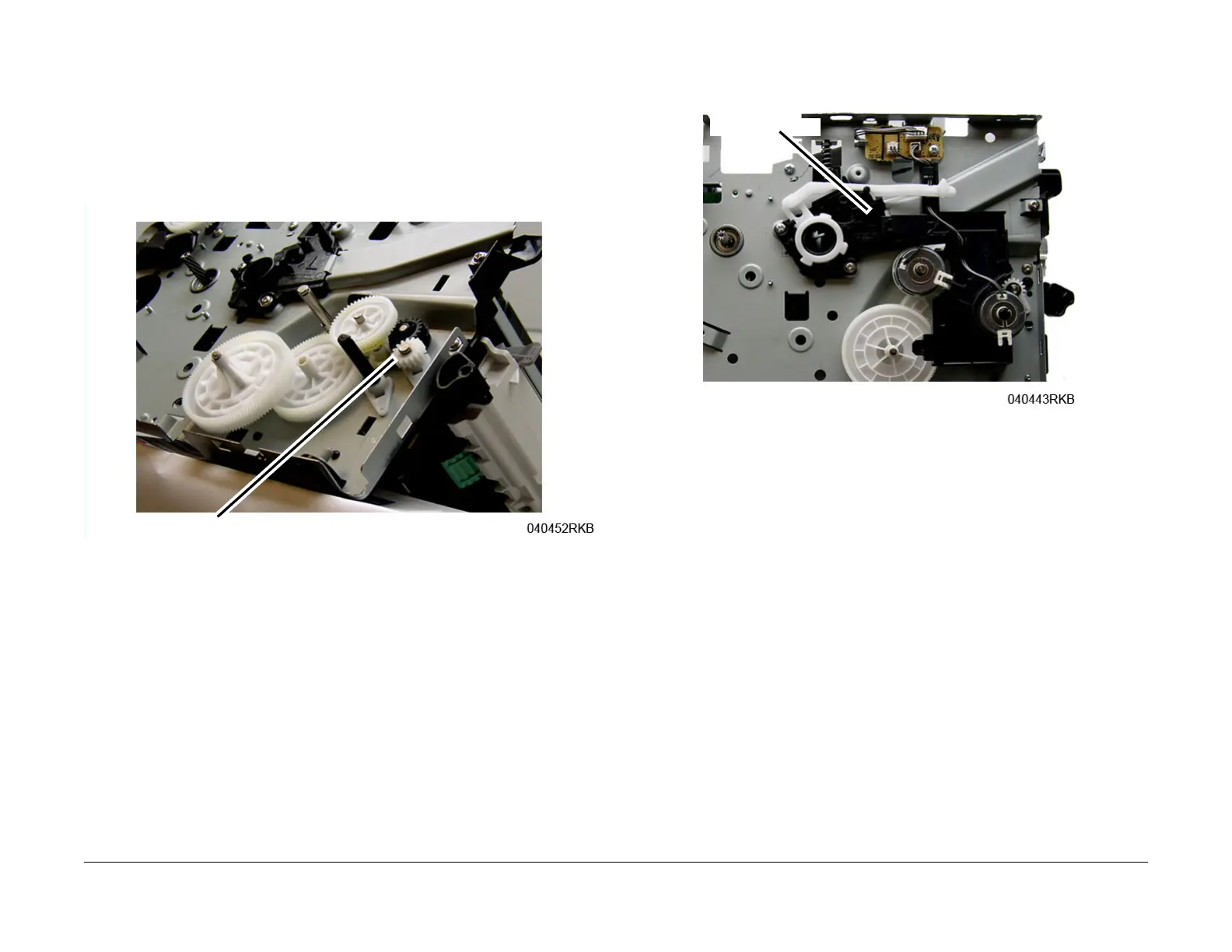
f. Install the Drive Gears and Snap Ring.
Figure 8 Feed and Registration Drive Gears
6. Install the remaining components in the reverse of removal.
When installing the Front Cover Support Arm make sure it is correctly placed on the St
op
Brac
ket, Figure 9
.
Figure 9 Front Cover Support Arm Placement
 Loading...