July 2019
4-53
Xerox® B205/B215 Multifunction Printer Service Manual
REP 4.17, REP 4.18
Repairs / Adjustments
Initial Release
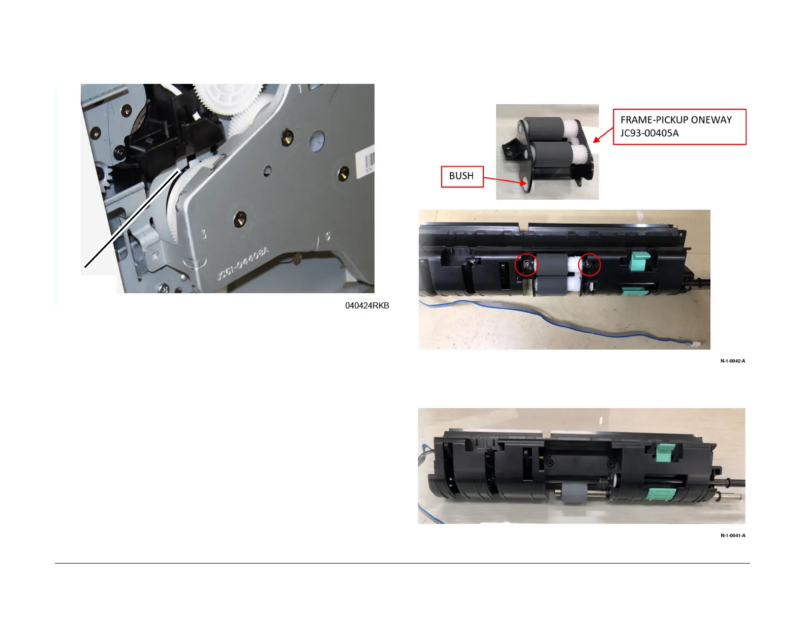
NOTE: Make sure the Tabs (2) on the Locking Lever are inside the Frame cutouts before
moving the Fuser Drive Locking Lever to the Lock position.
3. Align the Locking Lever Tabs (2) to the cutouts in the frame, F
igure 3.
Figure 3 Locking Lever Tab and Frame Cutout
4. Press in on the Locking Lever to move the Tabs into the cutouts.
Move the Locking Lever to the Lock position (Left).
5. Install the remaining components in the reverse of removal.
REP 4.18 Pick Up Assembly
Parts List on PL 4.5
Removal
1. Remove two screws, remove the one-way pickup frame from the upper pickup guide, then
rem
ove the bushing from the one-way pickup frame, Figure 1
.
Figure 1 One-way pickup frame and bushing removal
2. Remove the pickup guide from the upper pickup guide, F
igure 2.
Figure 2 Pickup guide removal
Locking Lever
Tab and Cutout
 Loading...