July 2019
4-49
Xerox® B205/B215 Multifunction Printer Service Manual
REP 4.15
Repairs / Adjustments
Initial Release
Replacement
NOTE: Tapered plastic screws and round machine screws are used to hold the cover to the
frame. Make sure that the plastic screws go into plastic components and machine screws go
into the metal frame.
1. Install the new Drive Motor.
NOTE: The Frame is flexible and can be bowed out if the screws are not tightened in t
he
corr
ect order.
Reinstall the Frame as follows so it seats f
lush against the printer’s internal modules.
2. Align the Frame on to the internal modules and shafts.
NOTE: Do Not fully tighten the screws in Step 3 until instructed.
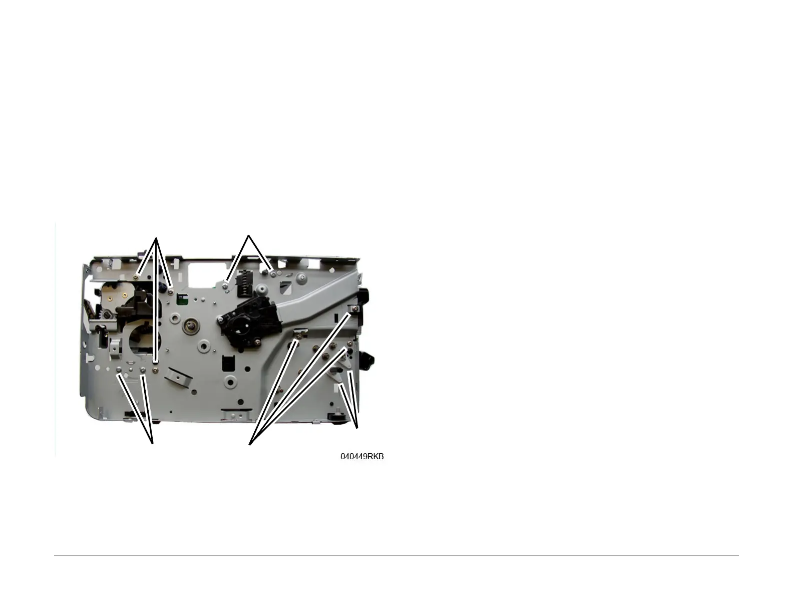
3. Install, but do not tighten, the following module screws, F
igure 7:
a. The Exit Sensor Plate screws (2).
b. The Front Paper Path Module screws (3).
Figure 7 Frame Screw Installation
4. On the bottom of the Printer, install the ground clip with the screw, then connect the Driv
e
Mot
or connector, Figure 7
.
Step 3a
Step 5b
Step 5c
Step 3b
Step 5e
 Loading...