July 2019
4-48
Xerox® B205/B215 Multifunction Printer Service Manual
REP 4.15
Initial Release
Repairs / Adjustments
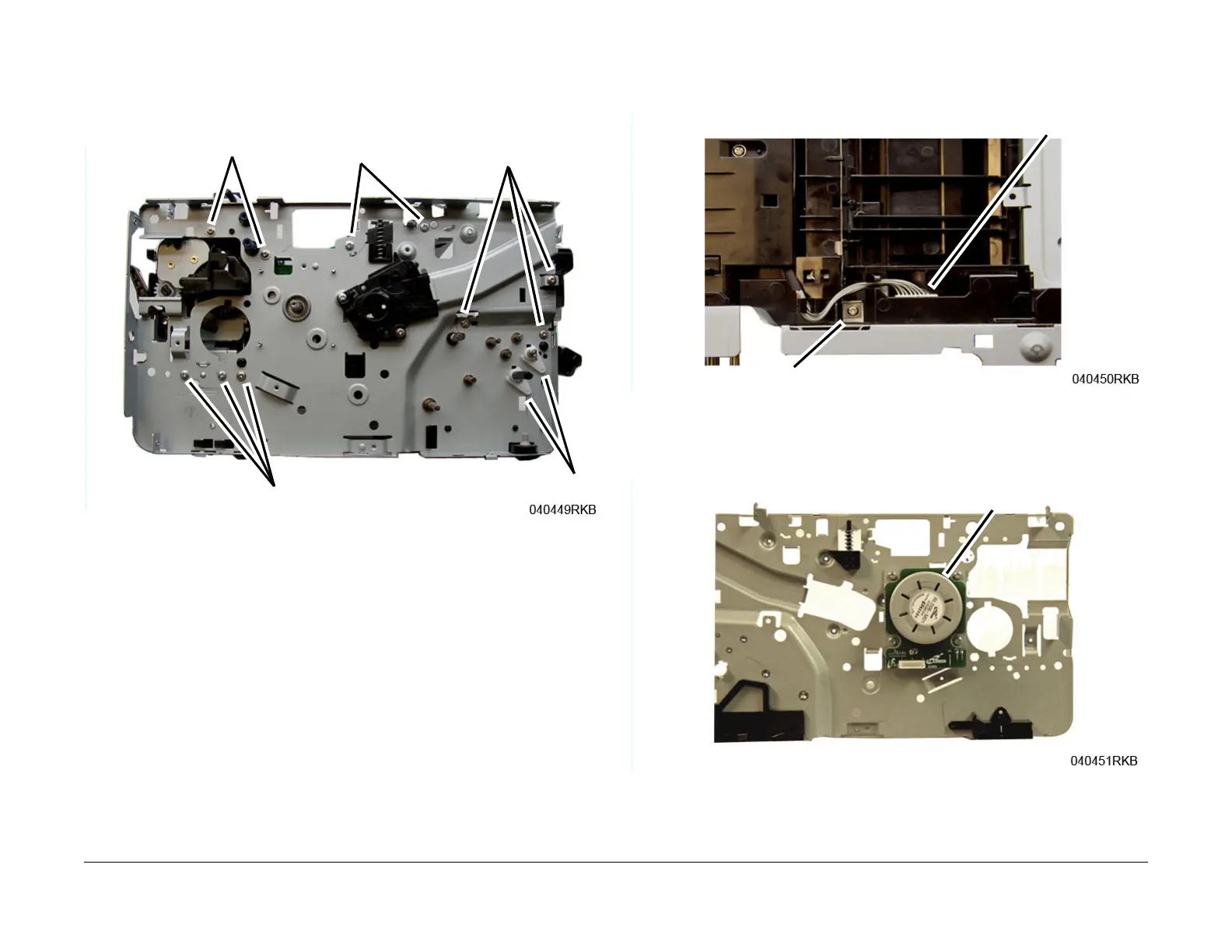
11. Remove the following from the Left Frame, Figure 4:
a. Shaft Bushings (2), release the latches.
b. LSU Assembly Support (2 screws).
c. Paper Path Module screws (5).
Figure 4 Left Frame parts removal
12. On the bottom of the Printer, F
igure 5:
a. Disconnect the Drive Motor Connector.
b. Remove the screw (1) and the Ground Clip.
Figure 5 Drive Motor Connector & Ground Clip (Bottom View)
13. Remove three screws attaching the Left Frame.
14. Remove four screws, then remove the Drive Motor, F
igure 6.
Figure 6 Drive Motor
Step 8b
Step 8c
Step 8c
Step 11
Step 8a
 Loading...