July 2019
4-26
Xerox® B210 Service Manual
REP 4.9
Initial Release
Repairs - Adjustments
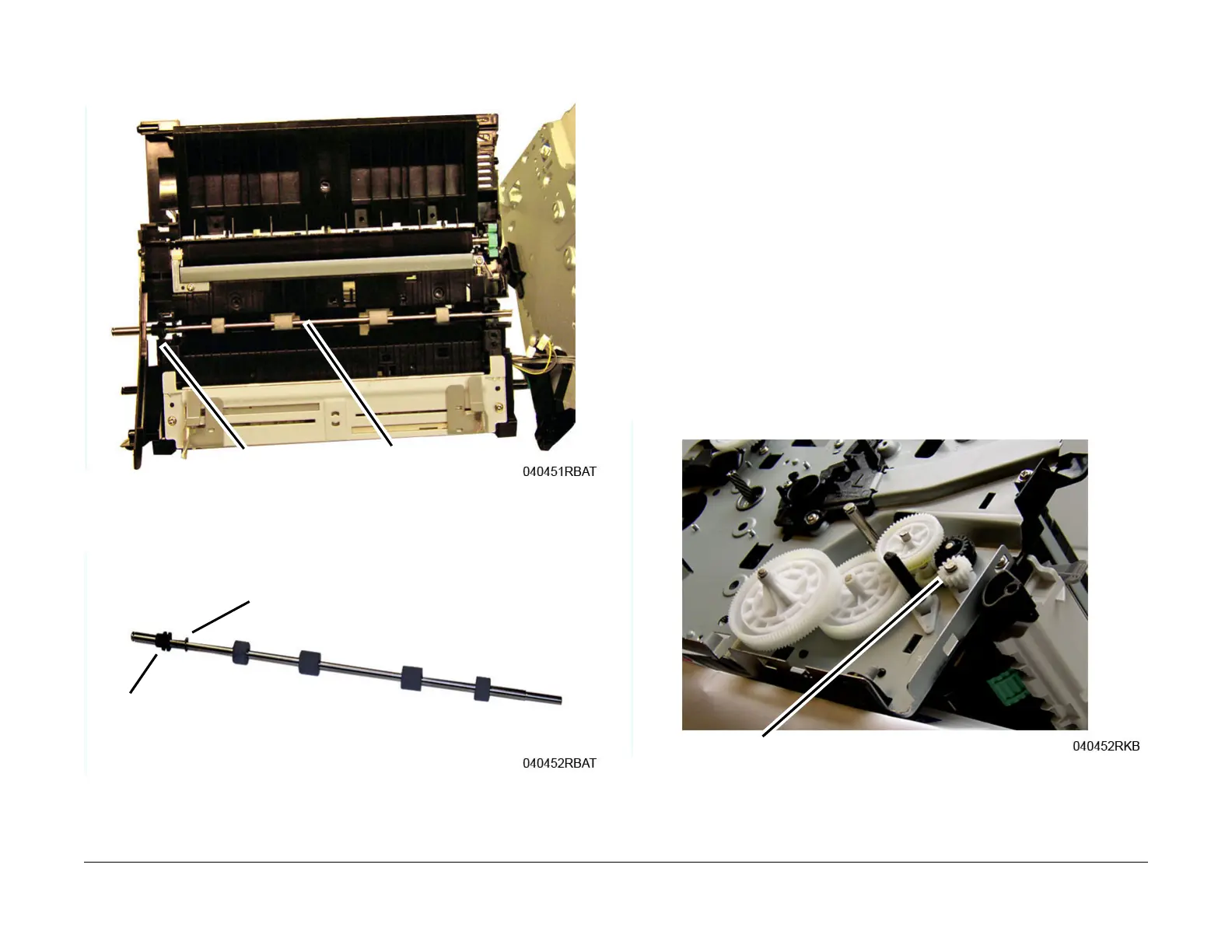
21. Remove the Registration Roll from the Middle Frame noting the location of the bushing,
Figure 15
.
Figure 15 Registration Roll Removal
22. Remove the Bushing and E-ring from the Registration Roll, F
igure 16.
Figure 16 Registration Roll
Replacement
Replacement is the reverse of the removal procedure.
NOTE: Tapered Plastic Screws and Round Machine Screws are used t
o hold the parts to the
frame. Make sure that the Plastic Screws go into plastic components and Machine Screws go
into the metal frame.
Assemble the frame:
NOTE: The Frame is flexible and can be bowed out if the screws are not tightened in the cor-
rect order.
1. Align the left and right frames together with the paper path modules; install, but do not
t
ighten, the three Middle Frame screws on each side of the printer. Refer to, Figure 14
and
F
igure 15, in the removal procedure.
2. Loosely install, the three Middle Frame screws on each side of the printer. Refer to, F
igure
14 and F
igure 15, in the removal procedure.
3. On the bottom of the printer, install the ground screw, then connect the drive motor con-
nector. Refer to, F
igure 8 in the removal procedure.
4. Tighten the three Middle Frame screws installed in Step 1.
5. Install the Paper Feed Sensor Actuator, ensure t
he spring is properly seated in the frame
c
utout. Refer to, Figure 7 in the removal procedure.
6. Install the Feed and Registration Drive Gears and snap ring. Refer to, F
igure 17.
Figure 17 Feed and Registration Drive Gears
 Loading...